36
SERVICE (CONT.)
Water Pump Relay
FIG. 37 RELAY
4. Disconnect and isolate the 120 VAC wires on the
relay contact terminals.
Check relay contact terminals for continuity when relay
coil is activated by the corresponding handle. The meter
on the display should show 0.00 or audible tone.
If continuity or voltage is not present as described,
replace the relay.
Removal and Replacement:
1. Disconnect the wires from the relay.
2. Remove the two nuts securing the relay to the
mounting bracket. Remove and discard relay.
3. Install the new relay to the mounting bracket using
two nuts.
4. Refer to Fig. 38 to reconnect the wires.
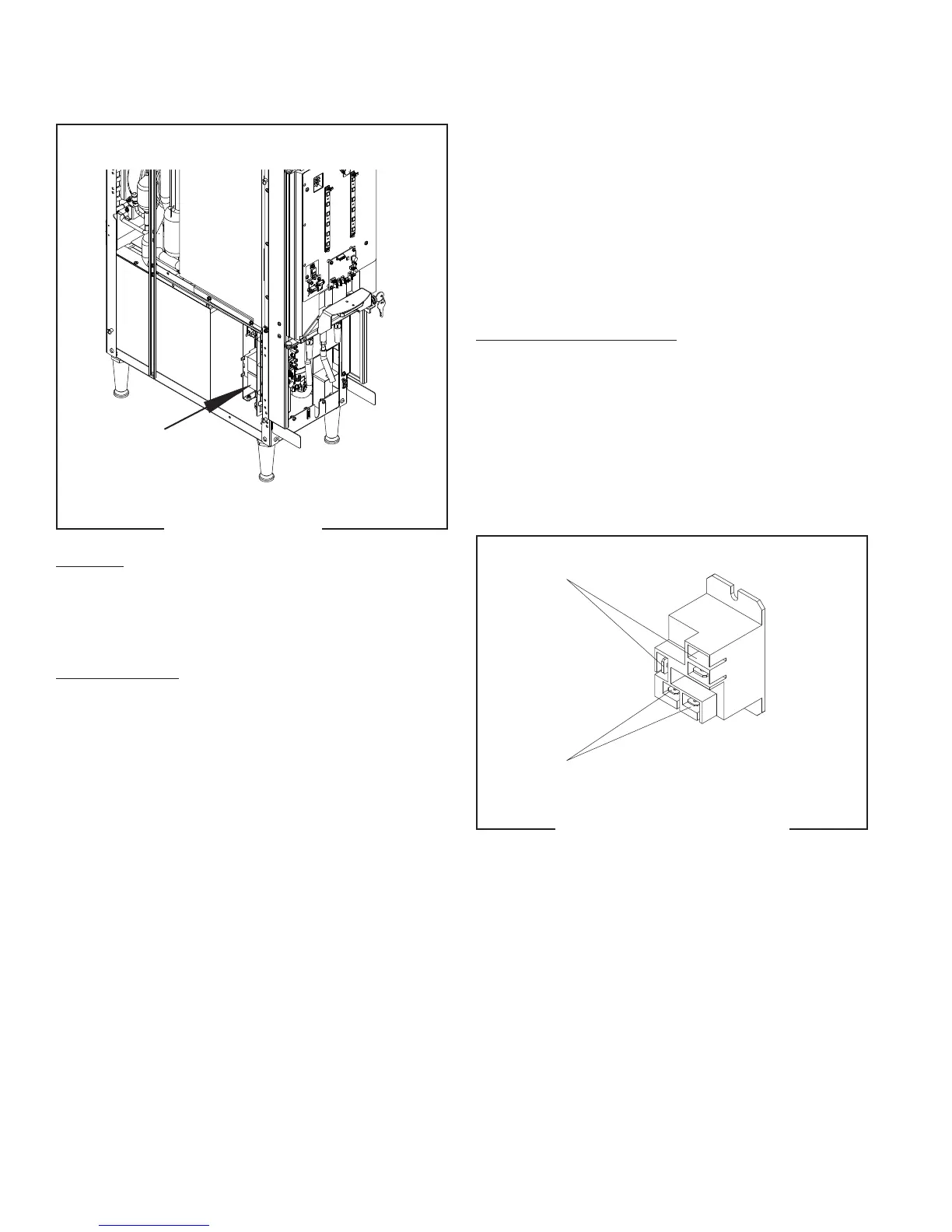
Location:
The relay (or contactor) is located inside the dis-
penser chassis on the lower outside of the component
bracket.
Test Procedures: Continuity or Voltage Check
The coil is supplied with 24VDC from the control board
while the relay contact terminal has 120VAC on the
black wire.
1. Disconnect the wires going to the coil.
2. Install red meter lead into the solid yellow wire
spade terminal (+) and black meter lead into the
pink wire spade terminal (-).
3. Pull a handle, the meter display should show a
voltage reading 24.0 to 30.0VDC.
The relay contact terminal is a normally open contact
and will close upon 24VDC activation of the coil. Ensure
wires are attached to coil terminals.
FIG. 38 RELAY TERMINALS
Contacts
Coil
55124 021418