44
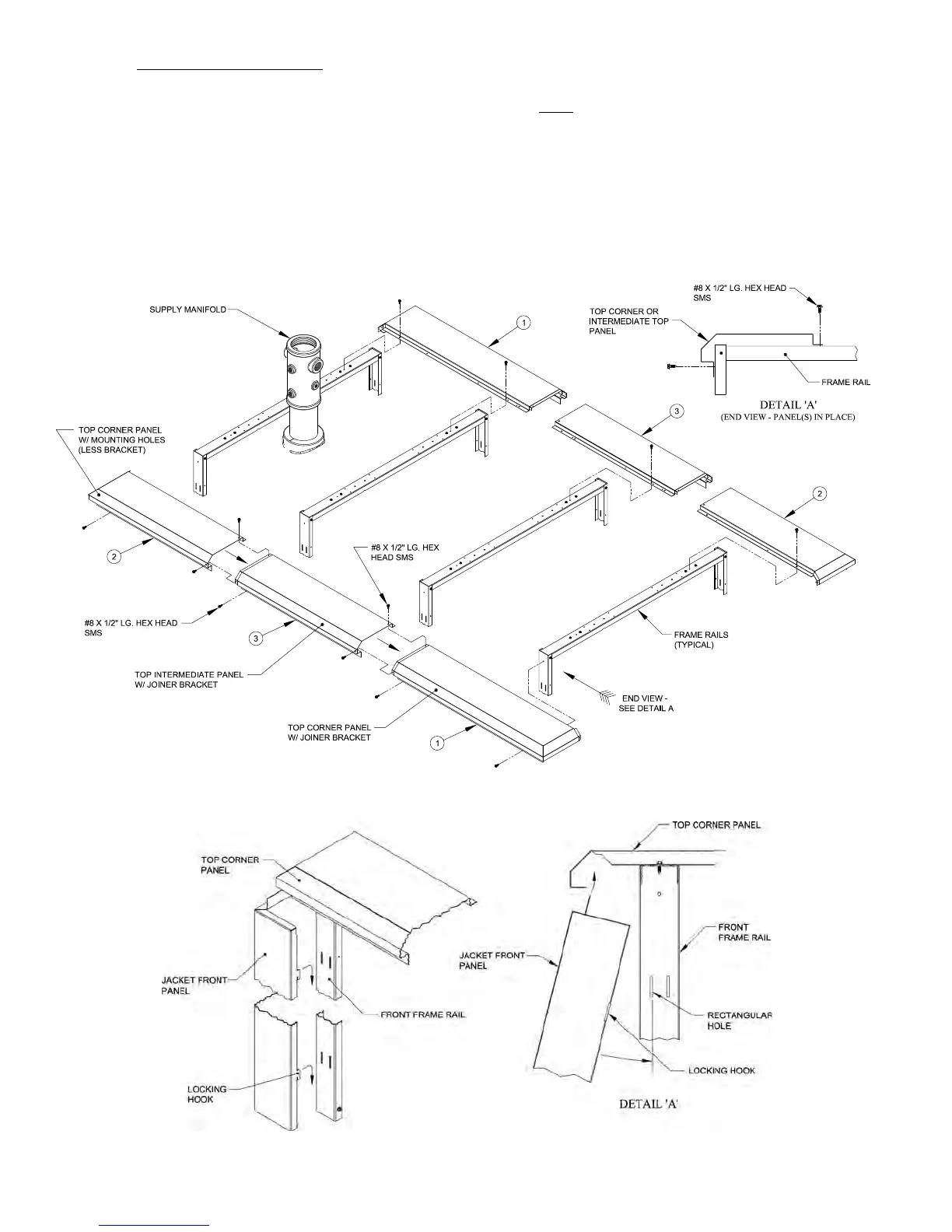
On 12 thru 18 Section Boilers, locate top
intermediate panel(s) #3 per Table X and secure to
panel #1 and each other using two (2) #8 x ½” lg.
hex head SMS per joint. Align mounting holes in
panel(s) #3 with holes in frame rails and secure with
two (2) #8 x ½” lg. hex head SMS per rail.
Locate top corner panel #2 per Table X and secure
to last top intermediate panel #3 installed, using two
(2) #8 x ½” lg. hex head SMS. Secure panel #2 to
rear frame rails using two (2) #8 x ½” lg. hex head
SMS.
Repeat same procedure as Steps 1 thru 5 to
install outer top panels to right side frame rails.
Note: Right side of boiler uses same panels as left
side with a reverse pattern starting at the rear
and working forward.
Locate Front Panel Shipped in Jacket Carton marked
‘JC-1’ - Position jacket front panel against front of
boiler assembly and feed internal harness wires through
holes in side of panel as shown in Figure 25.
Figure 26: Install Top Corner / Intermediate Panels
Figure 27: Install Jacket Front Panel