23
5. TURN “OFF” BURNER and remove pressure
gauge. Install gauge port plug and tighten. Start
burner again.
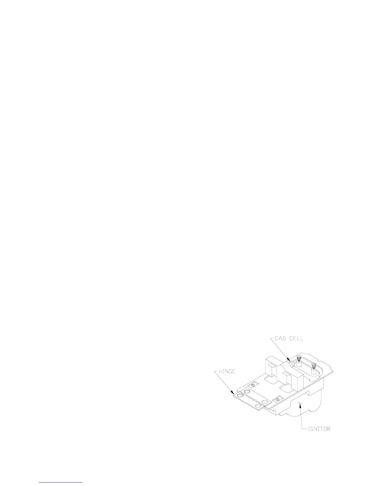
6. CAD CELL LOCATION AND SERVICE
The burner is supplied with a cadmium sulfide
flame detector mounted at the factory, mounted on
the bottom of the ignitor. See Figure 25. To service
cad cell or to replace the plug in portion, swing
open the ignitor. After service is complete, be sure
to fasten down the ignitor.
7. FLAME FAILURE
The V7 boiler controls operate the burner
automatically. If for unknown reasons the burner
ceases to fire and the reset button on the primary
control has tripped, the burner has experienced
ignition failure. Before pressing the reset button
call your serviceman immediately.
Fig. 24: "L1" and "V1" Head Electrode Positioning and Gun Setting (Beckett AFG)
(Non-Burnham Drawing,
Copy from LE Manual, 81433010R4, Page 13, without
"Figure 12A, 12B, 12C and 12D"; sample enclosed)
Figure 25: Cad Cell Location
 Loading...