-10-
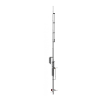
DRIVEN ELEMENT ASSEMBLY
20. Install 12M rod clamp (NN) to the right of 12M rod clamp (MM) and secure with 1" bolt, lock
washer and hex nut.
21.
Position the 12M rod (LL) in 12M rod clamps (NN) and (MM), securing it with 3/4" bolts, lock
washers and hex nuts.
22. Center capacitor clamp (KK) on the small tube of capacitor (FF) and secure with 3/4" bolt, lock
washer and hex nut.
23.
Position capacitor clamp (HH) 9 1/2 in (24.1 cm) from capacitor clamp (KK) and secure with 3/4"
bolt, lock washer and hex nut.
24. Attach the above assembly to 12M rod (LL) and position capacitor clamp (KK) 23 in (58.4 cm)
from 12M rod clamp (MM) and secure with 3/4" bolt, lock washer and hex nut.
25.
Secure the other capacitor clamp (HH) on above assembly to element tube (A) with 1" bolt, lock
washer and hex nut.
26. Install SO-239 connector (O) to tube (I) and secure it with 3/4" bolt, lock washer and hex nut.
Attach the free end of SO-239 connector (O) to tube (H) and secure it with 3/4" bolt, lock washer
and hex nut.
27.
Install the matching coil clamps (Q), one on tube (I) and the other on tube (H) and secure both with
3/4" bolts, lock washers and hex nuts.
NOTE: The gap between tube (H) and tube (I) is not critical but must be greater than 1".
28. Position driven element matching coil (P) between matching coil clamps (Q) and secure with 3/4"
bolts, lock washers and hex nuts.
This completes assembly of the driven element. Carefully check initial set-up dimensions making sure
everything is tight and set assembly aside.