-9-
Band Segment (15 & 10 Meters) Spacing
Low (CW) Segment 9 3/8 in (23.8 cm)
Middle Segment 9 1/2 in (24.1 cm)
High (Phone) Segment 10 1/8 in (25.7 cm)
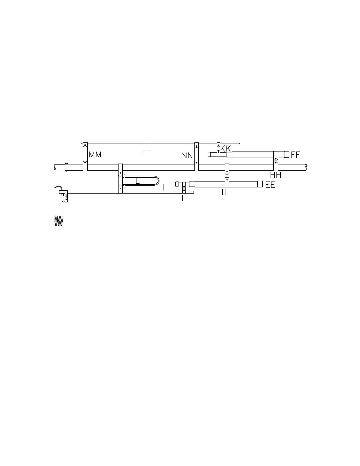
DRIVEN ELEMENT ASSEMBLY
8. Center 17M coil to cap clamp (OO) on the small tube of capacitor (FF) and secure with 3/4" bolt,
lock washer and hex nut.
9.
Position capacitor clamp (JJ) 6 7/8 in (17.5 cm) from 17M coil to cap clamp (OO) on capacitor (FF)
and secure with 1" bolt, lock washer and hex nut.
10. Install the above assembly on tube (H) as shown. Secure with 3/4" bolt, lock washer and hex nut.
11. Position 17M coil clamp (QQ) 16 1/2 (41.9 cm) from 17M coil to cap clamp (OO) on tube (H) and
secure with 3/4" bolt, lock washer and hex nut.
12.
Install 17M coil (PP) between 17M coil clamp (QQ) and 17M coil to cap clamp (OO) and secure
with 3/4" bolts, lock washers and hex nuts.
13.
Place a second 4-way clamp around the right element tube (A). Using the chart below, position it
from element tube insulator (B). Secure with a 1" bolt, lock washer and hex nut.
14. Install tube (I) on the right side of the element as shown. Secure it with 3/4" bolt, lock washer and
hex nut finger tight.
15.
Center capacitor clamp (II) on the small tube of capacitor (EE) securing it with 3/4" bolt, lock
washer and hex nut.
16. Attach capacitor clamp (HH) to capacitor (EE) and position it 7 in (17.8 cm) from capacitor clamp
(II). Secure it with 3/4" bolt, lock washer and hex nut.
17.
Attach the above assembly to element tube (A) and position capacitor clamp (HH) 28 3/8 in (72.1
cm) from the element tube insulator (B). Secure capacitor clamp (II) with 3/4" bolt, lock washer
and hex nut and capacitor clamp (HH) with 1" bolt, lock washer and hex nut.
18. Install u-shaped stub (L) on the 4-way clamp located on the right element and secure with 3/4" bolts,
lock washers and hex nuts.
19.
Position 12M rod clamp (MM) on the right element tube (A) 3 1/4 in (8.3 cm) from element tube
insulator (B) and secure with 3/4" bolt, lock washer and hex nut.