-11-
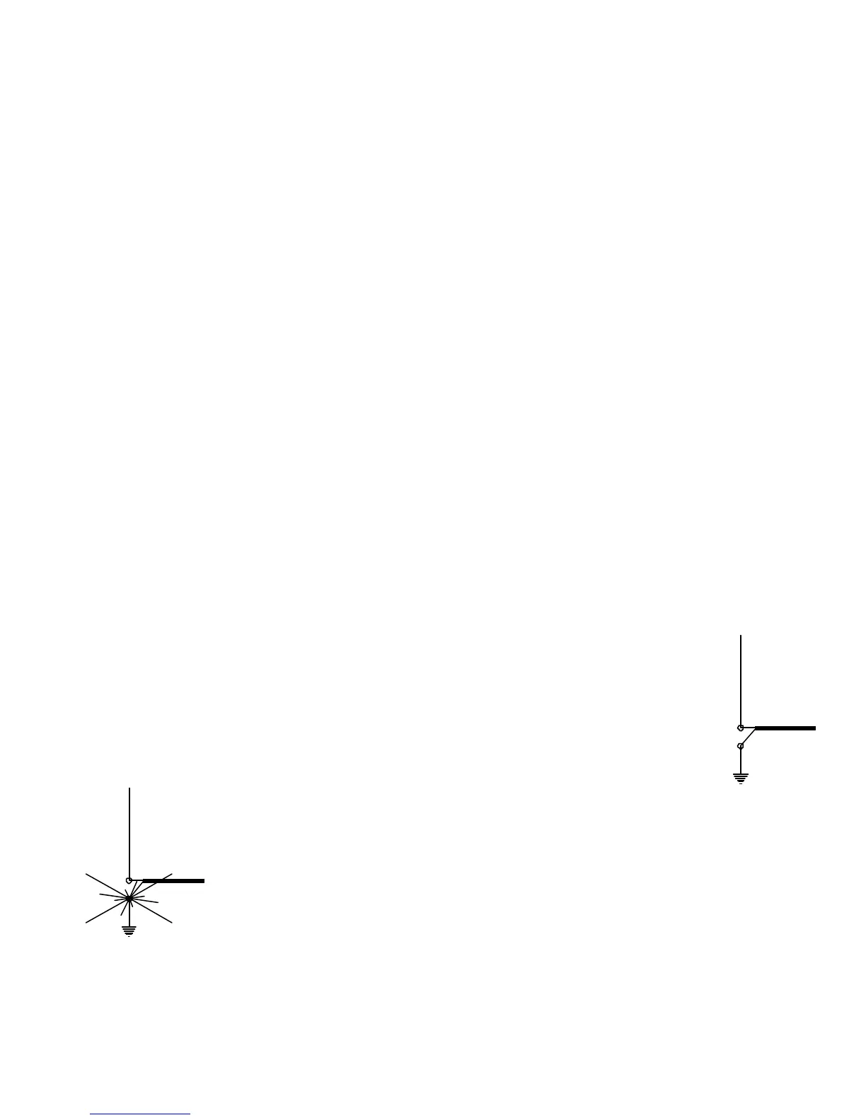
Figure 1
Figure 2
TECH NOTES—GROUND RADIAL SYSTEMS
MOUNTING TUBE INSTALLATION
When tube w/insulator (A) is ground mounted, it should be protected against corrosion if placed
in concrete, damp acidic or alkaline soil. Asphalt roofing compound, polyurethane varnish or
other sealant that protects against moisture may be used.
Concrete may be used in areas of high winds for greater strength, in which case the post may
be twisted slightly during setting for easy removal later.
Tube w/insulator (A) must be installed in a hole approximately 21 in (53.3 cm) deep so that the
upper end of the fiberglass insulator is approximately 7 in (17.8 cm) above ground level. Pack
earth tightly around tube w/insulator (A) so that it remains vertical.
NOTE: HAMMERING TUBE W/INSULATOR (A) INTO THE EARTH MAY CAUSE THE INSULATOR
TO SPLINTER. If the post must be hammered into the earth, protect the end of the insulator
with a block of wood
NOTE: DO NOT USE U-BOLTS TO ATTACH TUBE W/INSULATOR (A) TO A MAST, TOWER ETC.
U-BOLTS WILL EVENTUALLY CUT INTO THE TUBING AND WEAKEN THE INSTALLATION. If
U-bolts must be used, place a larger diameter metal, such as the MPS Mounting Post Sleeve
over tube w/insulator (A). Similar precautions should be observed when using TV style towers
with locking bolts.
The RMK-II Roof Mounting Kit includes the MPS as well as the STR-II Stub Tuned Radial Kit.
GROUND MOUNTING
A vertical antenna in its simplest form, is electrically equivalent to one-half
of a dipole antenna stood on end. When the antenna is mounted close to
the ground, the earth below takes the place of the "missing" half of the
dipole. If ground conductivity is fair to good, a short metal stake or rod
may provide a sufficiently good ground connection for resonant and low
SWR operation on the bands for which the antenna is designed. This basic
arrangement is shown in figure 1.
The way it works is that the capacitance between the
vertical radiator and the ground causes return currents
to flow along the earths surface back to the transmitter. If they have to
come back along untreated lossy earth thy get back to the source greatly
attenuated. This return loss is like a resistor in series with the antenna
radiation resistance and will therefore affect the feed point impedance.
In almost every case the efficiency of a vertical antenna will be greater if
radial wires are used to improve ground conductivity as in figure 2. It’s
important to note that there’s no point in cutting radials to any particular
length when ground mounting because the earth will detune them anyway.
All you want to do is make the surface of the earth around the antenna more conductive than it
is ordinarily.