-13-
Figure 3
TECH NOTES—GROUND RADIAL SYSTEMS
the efficiency would be 15/35=43%. From the above calculations it is clear that the shorter a
vertical antenna must be the less efficient it also must be for a given ground loss resistance.
Or to state the matter another way, more elaborate ground or radial systems must be used
with shorter verticals for reasonable efficiency. If the ground loss of resistance of 15 ohms
from the preceding example could be reduced to zero ohms, it is easy to show that the
efficiency of our one-eighth wavelength loaded vertical would increase to 75%. Unfortunately,
more than 100 radials each one-half wavelength long would be required for zero ground loss,
so lower efficiencies with shorter radials must usually be accepted for the sake of
convenience. In spite of their limitations, short vertical antennas over less than ideal ground
systems are often more effective DX performers than horizontal dipoles which must be placed
well above the earth (especially on the lower bands) to produce any significant radiation at the
lower elevation angles. Verticals, on the other hand, are primarily low-angle radiators on all
bands.
ABOVE GROUND (ELEVATED) INSTALLATIONS (rooftop, tower, mast. etc.)
The problem of ground loss resistance may be avoided to some extent by mounting a vertical
antenna some distance above the earth over an artificial ground plane consisting of resonant
(usually 1/4 8) radial wires. Four resonant radials are considered to provide a very low-loss
ground plane system for vertical antennas at base heights of 1/2 8 or more. This arrangement
contrasts favorably with the more than 100 radials for zero ohms loss resistance at ground
level, and since 1/2 8 is only about thirty-five feet at 20 meters, very worthwhile improvement
in vertical antenna performance can be realized, at least on the higher bands, with moderate
pole or tower heights. At base heights below 1/2 8 more than four radials will be required to
provide a ground plane of significantly greater conductivity than the lossy earth immediately
below the antenna: even so, a slightly elevated vertical with relatively few radials may be more
effective than a ground-level vertical operating over a larger number of radials if only because
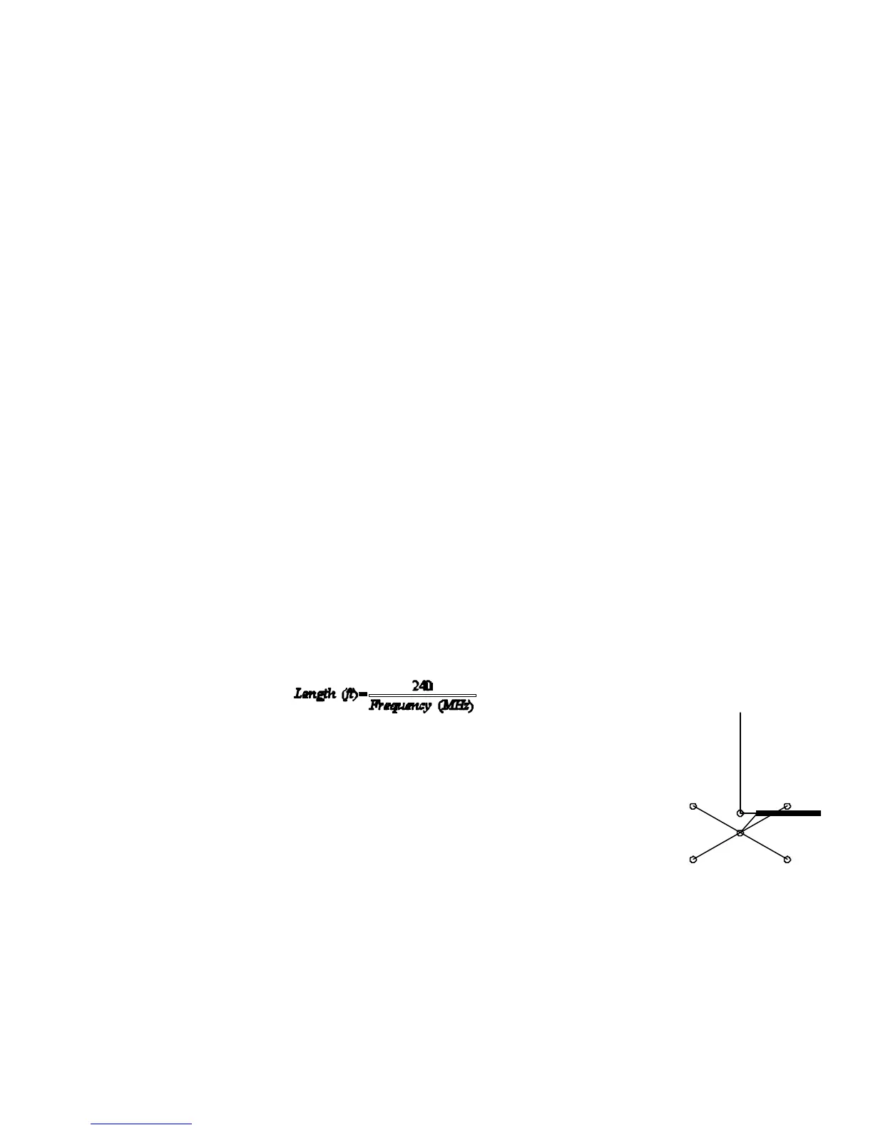
the former is apt to be more in the clear. Resonant radial lengths for any band may be
calculated from the formula:
Figure 3 shows the basic ground plane system for elevated verticals.
Radials may slope downward as much as 45 degrees without any
significant effect on operation or performance. Radials for different bands
should be separated as much as possible and the far end of each radial
insulated from supporting wires. Figure 4 shows a ground plane system
that uses four resonant radials for 40 meters, another set of four for 20
meters, and a third set for 10 meters. A separate set for 15 meters is not
ordinarily required because the 40 meter radials operate as resonant 3/4 8
radials on that band. At the lower heights the separate wires of this
system may provide enough capacitance to ground to permit low SWR
operation on 80/75 meters as well, but it is probable that at least one resonant radial will be
required for low SWR on that band. It’s important to note that cutting each conductor of
rotator cable to a specific frequency will not work unless you separate it, angling each
conductor away for most of its length because the longer ones will detune the shorter ones.
 Loading...