-6-
CHECKOUT AND ADJUSTMENT
or less at the low end of the band and may be as much as 100 kHz at the high end of
the band, depending on the efficiency of the ground system used, greater bandwidth
being associated with lossy ground systems. It should be remembered that on those
bands where the physical height of a vertical antenna is less than a quarter
wavelength, the earth (or the resonant radial system in above-ground installations) will
have a good deal to do with VSWR and antenna tuning, bandwidth and overall
performance.
Low VSWR by itself does not mean that a vertical antenna is operating efficiently, and
if low VSWR is obtained with no more than the usual quick and dirty ground
connection, it most likely means the opposite. In general, poor operation or improper
tuning of vertical antennas can usually be attributed to inadequate (or even reactive)
ground systems or to other vertical conductors in the vicinity of the antenna. For
these reasons it is suggested that the antenna be placed as much in the clear as
possible and used with the best ground system that conditions permit. For a more
complete discussion of the interrelationships between vertical antenna efficiency,
bandwidth, VSWR, etc., a standard text such as the A.R.R.L. Antenna Book is
recommended. See also the material included at the end of these instructions.
For adjustment purposes a simple VSWR indicator may be used. More accurate
measurements may be made at the antenna (i.e., at the junction of the coax 75 ohm
matching (R) and the main transmission line) than at the input end of the line, but the
tuning conditions that exist at the transmitter will usually be of greater interest in that
one's principal concern will be to couple power from the transmitter into the
transmission line.
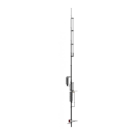
1. Determine the frequency at which VSWR is lowest on 80/75 meters. The coil
setting given earlier should produce resonance and lowest VSWR at approximately
3700 kHz. To raise the frequency of resonance of the lowest VSWR, simply
loosen the wing nut on the lower coil clamp of the coil assembly 80/40 meter (C)
coil on tube (B) and stretch the coil a bit more. To lower the frequency, compress
the coil. A 1 in (2.5 cm) change in the setting of this coil will produce a frequency
shift of approximately 125 kHz.
NOTE: Remember that the antenna tunes very sharply in this range
and that high values of VSWR may be encountered only a few kHz
either side of the lowest VSWR readings, so it would be well to take
VSWR readings every 25 kHz or so to avoid running past the
frequency of resonance and lowest VSWR.
NOTE: To minimize interference to other stations and to avoid
erroneous reading use only enough power to produce full-scale
deflection of the meter in the forward or r.f. out position.
2. Once the proper coil setting has been found for the desired band segment, coil (Q)
base matching at the base of the antenna may be adjusted for even lower VSWR.
If earth losses are moderate to high a good match may be possible if coil (Q) base
matching is left fully compressed; if earth losses are low (as with an extensive
radial system) coil (Q) base matching may have to be stretched to twice its
compressed length or more for a good match. In any case, a single setting for coil
(Q) base
 Loading...