-5-
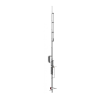
ASSEMBLY
35.
Place the protective cap on one end of tube (J).
36.
Slide the uncapped end of tube (J) into the slotted end of tube (I) until only 25 in
(63.5 cm) extends and secure with compression clamp small adjustable.
NOTE: In the following steps the antenna will be assembled and raised
to its full vertical height. If the antenna is to be installed in an elevated
position where it is unsafe or inconvenient to make in-place
adjustments, the antenna may have to be installed in one piece. It will
probably be necessary to raise and lower it and its supporting
structure a number of times to arrive at the ideal adjustment on all
bands. If so, every precaution should be observed in order to avoid
possible contact with power lines and to prevent structural failure that
can cause injury to persons or property.
37. Place the lower end of tube (B) through tube (E) over the insulator on tube (A)
w/insulator. Line up the holes and secure it with a # 8 x 2" screw, lock washer
and hex nut.
WARNING: AVOID POWER LINES!
38. Raise the assemble of tube (F) through tube (J) and slide the lower end into tube
(E) fastening it securely with a # 8 x 1 1/4" screw, lock washer and hex nut.
39. Install coax 75 ohm matching (R) as shown placing the lug from the center
conductor over the screw on tube (B) and the braid over the screw on tube
w/insulator (A).
40. Place # 8 washers over each screw and install coil (Q) base matching. Secure with
washers, lock washers and hex nuts.
NOTE: Attach radials and ground to tube w/insulator (A) using the
remaining # 8 hardware.
WARNING: MAKE SURE THAT THE STATION EQUIPMENT IS
CONNECTED TO A GOOD EARTH GROUND! DO NOT HANDLE CABLE
CONNECTED TO STATION EQUIPMENT WITHOUT FIRST
DISCONNECTING THE EQUIPMENT FROM THE POWER MAINS. YOU
COULD BE ELECTROCUTED!
41. Connect coax 75 ohm matching (R) to any length of 50-53 ohm coaxial cable.
Connector PL258 (S) is provided. Seal the connection with the small roll of
Konnector-Kote.
CHECKOUT AND ADJUSTMENT
The dimensions and coil settings given above should produce reasonably low VSWR
readings over the entire 10, 15, 20 and 30 meter bands and over at least 250 kHz of
the 40 Meter band. Bandwidth on 80/75 meters should be at least 30 kHz for VSWR
of 2:1