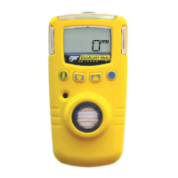
GasAlertMicroClip
Maintenance
13
Item Description
1 Front shell
2 LEL sensor
3 PCB
4 PCB screws (2)
5 Rear shell
6 Machine screws (6)
7 Sensor filter
8 O
2
sensor
9 H
2
S sensor
10 CO sensor
1. If the detector is activated, deactivate it.
2. Remove the six machine screws on the rear shell and
remove the back cover.
Note
Note the orientation of the battery PCB (bent up or laid flat).
3. Remove the two screws on the PCB and remove the
PCB.
Note
Ensure the battery does not get damaged once the PCB is
removed.
4. Remove the old sensor filter or slide/pull out the old
sensor(s).
5. Insert a new sensor filter or sensor(s).
Note
Detectors that are configured for 1, 2, or 3 gases may contain a
dummy sensor in one of the four sensor locations.
6. Re-assemble the detector. When assembling the
detector, be aware of the following:
• Ensure the charging contact pins inside the rear
shell are aligned with the corresponding hole
before inserting the rear shell in place. If the
contact pins are bent, the battery will not charge
properly.