User’s Manual
25
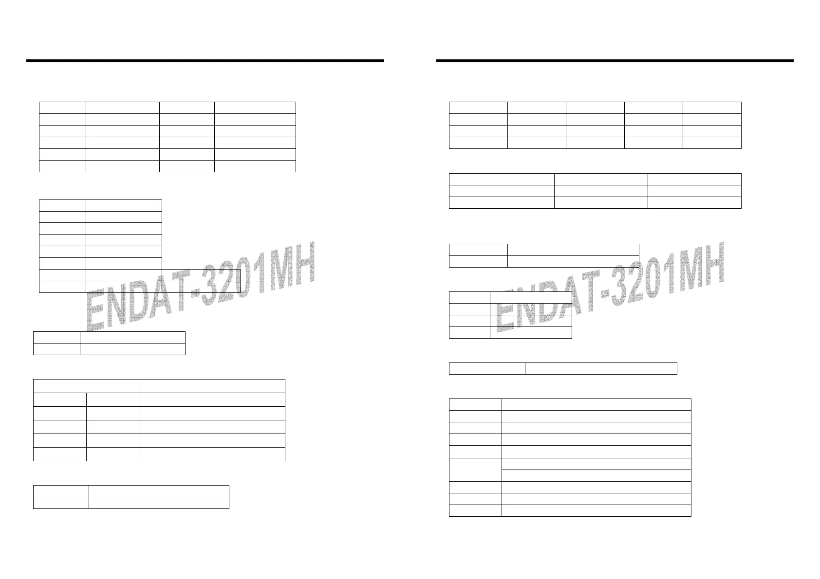
JUSB1 Header
Pin No. Description Pin No. Description
1 USB_VCC 2 USB_VCC
3 USB_DATA0– 4 USB_DATA1–
5 USB_DATA0+ 6 USB_DATA1+
7 USB_GND 8 USB_GND
9 USB_GND 10 USB_GND
JP20 KB-Controller interface Header for Special OEM design:
Pin No. Description
1 KB_JDT
2 KB_DATA
3 KB_JCK
4 KB_CLK
5 KEY
6 KB_VCC Add in Rev.1B
7 GND Add in Rev.1B
* Default close 1-2 and 3-4 for Normal operation.
JP2: CMOS Data Clear:
Pin 1-2 *
Normal
Pin 2-3
Clear CMOS Data
JP15: DiskOnChip Memory Address Selector
JP15 Memory Address
1-2 7-8
0C800H-0C9FFH
1-2 9-10
0CC00H-0CDFFH
3-4 7-8
0D000H-0D1FFH
3-4 9-10
0D400H-0D5FFH
5-6 7-8
0D800H-0D9FFH(Default)
JP3: On-board LAN Disable/Enable
Pin 1-2
Enable On-Board LAN
Pin 2-3
Disable On-Board LAN
26
The ENDAT-3201M/MF/MH
Embedded CPU Board
JP9 (COM1, 2) / JP4 (COM3, 4) Voltage Selector:
Voltage COM1(JP9) COM2(JP9) COM3(JP4) COM4(JP4)
+12V(DC) 1-2 7-8 1-2 7-8
R.I. 3-4 9-10 3-4 9-10
+5V(DC) 5-6 11-12 5-6 11-12
JP10, JP11: RS232 / 422 / 485 Selector for COM2
TYPE JP10 JP11
RS-232 1-2, 4-5, 7-8, 10-11 1-2
RS-422/485 Full Duplex 2-3, 5-6, 8-9, 11-12 3-4, 7-8
* Make sure the port mode is set up correctly before installing any peripherals.
JP12’s Pin 9~11: On-board Power Good Selector
Pin 9-10
Using External Power Good
Pin 10-11
Using On Board Power Good
JFAN1, JFAN2: CPU / 2nd Cooling Fan Connector
Pin No. Function
Pin 1 Sensor Pin.
Pin 2 +12V
Pin 3 GND
JP12’s Pin12;13: For ATX Power Supply
Pin 12; Pin 13 On/Off Switch for ATX Power
JP12: Case Panel Connection:
Pin No. Description
1,2 HDD_LED –/+
3,6 External Speaker
4,5 Onboard Buzzer
7-8 Hardware RESET
Reserved 9-10
10-11
Reserved
12-13 ATX Power On/Off
14-15 Power LED (14:LED+, 15:LED-)
19-20 Close: Enable WDT function
 Loading...