Chapter 2.
Setting up the CPU Motherboard
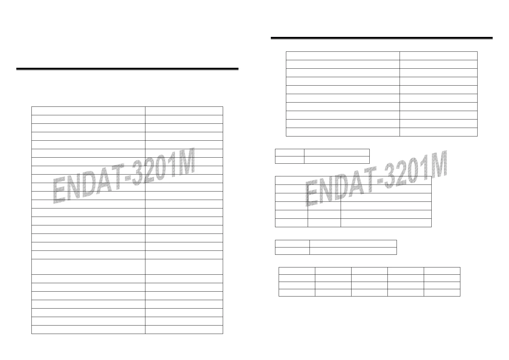
2-1. Jumpers and Connectors (ENDAT-3201M)
Jumpers/Connectors Overview:
Function Jumpers/Connectors
Cooling Fan Connector JFAN1, JFAN2
Power Supply: Power Good JP12: Pin 9~11
ATX Power On/Off Switch JP12: Pin 12~13
Audio Port Connector CN1
2
nd
Printer Port CN4
LAN Adapter Disable/Enable JP3
COM1 Port CN6
COM2 Port CN8
COM3 Port CN2
COM4 Port CN3
COM Ports Power Selector (COM1, 2, 3, 4) JP4, JP9
RS232/RS422/RS485 Selector (COM2) JP10, JP11
DiskOnChip Memory Address JP15
LCD: TFT LCD Panel Connector LCD-CON1
LVDS LCD Output Port CN5
LVDS Voltage Selector JP5
Clear CMOS JP2
Factory Setting
JP1, JP7, JP8, JP13, JP14, JT1,
JH1
PS/2 Keyboard Jack JKBMS
PS/2 Mouse Jack JKBMS
PS/2 Mouse/KB Pin Header CN7
IR J1
FDD Connector FDD1
IDE 1 IDE1
Header for Case Panel
JP12
10
The ENDAT-3201M/MF/MH
Embedded CPU Board
Function Jumpers/Connectors
IDE 1 LED JP12: Pin 1, Pin 2
External Speaker JP12: Pin 3, Pin 6
Buzzer On/Off JP12: Pin 4, Pin 5
Hardware Reset Switch JP12: Pin 7, Pin 8
External Power Good JP12: Pin 9, Pin 10
Internal Power Good JP12: Pin 10, Pin 11
ATX Power Supply On/Off Switch JP12: Pin 12, Pin 13
Power LED JP12: Pin 14, Pin 15
WDT Function Enable/Disable JP12: Pin 19, Pin 20
JP2: CMOS Data Clear:
Pin 1-2 *
Normal
Pin 2-3
Clear CMOS Data
JP15: DiskOnChip Memory Address Selector
JP15 Memory Address
1-2 7-8
0C800H-0C9FFH
1-2 9-10
0CC00H-0CDFFH
3-4 7-8
0D000H-0D1FFH
3-4 9-10
0D400H-0D5FFH
5-6 7-8
0D800H-0D9FFH(Default)
JP3: On-board LAN Disable/Enable
Pin 1-2
Enable On-Board LAN
Pin 2-3
Disable On-Board LAN
JP9 (COM1, 2) / JP4 (COM3, 4) Voltage Selector:
Voltage COM1(JP9) COM2(JP9) COM3(JP4) COM4(JP4)
+12V(dc) 1-2 7-8 1-2 7-8
R.I. 3-4 9-10 3-4 9-10
+5V(dc) 5-6 11-12 5-6 11-12