User’s Manual
11
JP10, JP11: RS232 / 422 / 485 Selector for COM2
TYPE JP10 JP11
RS-232 1-2, 4-5, 7-8, 10-11 1-2
RS-422/485 Full Duplex 2-3, 5-6, 8-9, 11-12 3-4, 7-8
* Make sure the port mode is set up correctly before installing any peripherals.
JP12’s Pin 9~11: On-board Power Good Selector
Pin 9-10
Using External Power Good
Pin 10-11
Using On Board Power Good
JFAN1, JFAN2: CPU / 2nd Cooling Fan Connector
Pin No. Function
Pin 1 Sensor Pin.
Pin 2 +12V
Pin 3 GND
JP12’s Pin12;13: For ATX Power Supply
Pin 12; Pin 13 On/Off Switch for ATX Power
JP12: Case Panel Connection:
Pin No. Description
1,2 HDD_LED –/+
3,6 External Speaker
4,5 Onboard Buzzer
7-8 Hardware RESET
Reserved 9-10
10-11
Reserved
12-13 ATX Power On/Off
14-15 Power LED (14:LED+, 15:LED–)
19-20 Close: Enable WDT function
J1: IR Pin Header.
Pin No. Function
1 +5V(DC)
2 N.C.
3 IRRX
4 GND.
5 IRTX
12
The ENDAT-3201M/MF/MH
Embedded CPU Board
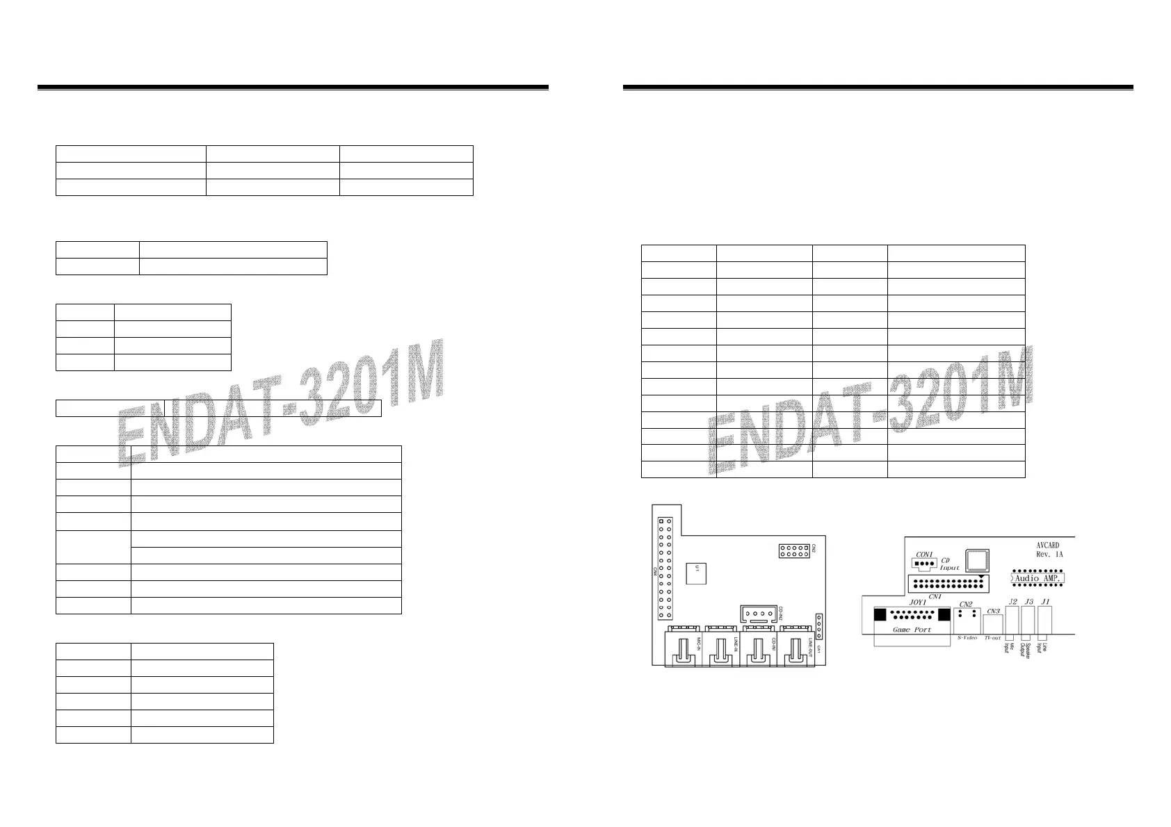
CN1: Audio Output Port connector via AV Card Kit (Optional)
Please close pin13-14 to disable onboard Audio features if the AV Card Kit is not
inserted onto the CN1 connector. If AV card kit is inserted, please make sure the
BIOS is enabled with the audio function, since LPT2 and audio function can not be
used in the same time.
CN1: Audio Port.
Pin No. Function Pin No. Function
1 BITCLK 2 GND
3 SDIN 4 N.C.
5 SDIN2 6 N.C.
7 SDOUT 8 N.C.
9 SYNC 10 GND
11 –ACRST 12 GND
13 SPEAK 14 Strapping Low
15 +5V(DC) 16 +12V(DC)
17 JBCY 18 JAB2
19 JBCX 20 JAB1
21 JACY 22 JBB2
23 JACX 24 JBB1
25 MSO 26 MSI
AV Card
UC-A003