Aircraft Overview
Citation Bravo Developed for Training Purposes 5A-17
July 2004
The single-assembly horizontal sta-
bilizer is on the vertical stabilizer
above the fuselage tail section. The
horizontal stabilizer incorporates the
elevators. The horizontal stabilizer
leading edge has pneumatically
inflated deice boots for ice protec-
tion (see Ice and Rain chapter).
A structural honeycomb panel at the
lower end of the vertical stabilizer
provides access to elevator and rud-
der control cables and components,
avionics flux detector cable assem-
bly connectors, and deice boot
assemblies.
A saddle assembly at the lower lead-
ing edge of the vertical stabilizer
provides a smooth contour between
the dorsal fin and vertical stabilizer.
The locator beacon antenna mounts
on the saddle assembly, while the
optional emergency locator transmit-
ter (ELT) is in the dorsal fin. The
rudder is on the vertical stabilizer
trailing edge (see Flight Controls
chapter).
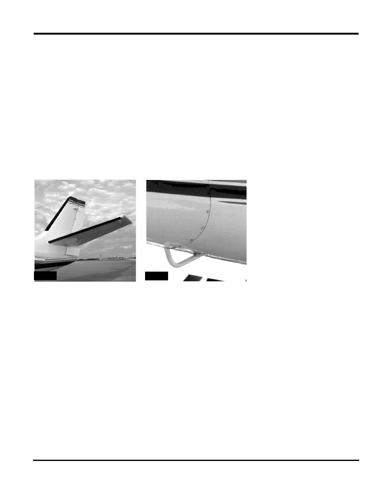
A tailskid on the lower aft portion of
the tail section (Figure 5A-28) pre-
vents fuselage damage if overrota-
tion occurs.