5A-16 Developed for Training Purposes Citation Bravo
July 2004
CAE SimuFlite
The wing fixed leading edge (Fig-
ure 5A-23) supports two wing ice
protection systems: the outboard
leading edge pneumatically inflated
deice boots and the inboard leading
edge electric heating elements; stall
strips are attached to the deice boot.
A cable-operated outboard aileron
and one electrically operated inboard
flap are on each wing trailing edge.
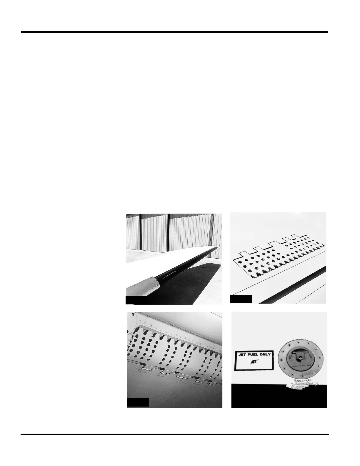
Speedbrakes are on the upper (Fig-
ure 5A-24) and lower (Figure 5A-
25) surfaces of the wing, just for-
ward of the outermost flaps.
Fuel Tanks
An integral tank in each wing supplies
fuel to its respective engine or cross-
feeds to the opposite engine, as
selected. Each 360 gallon tank has an
overwing fueling port (Figure 5A-26).
Except for the area above the main
landing gear wheel well, the integral
fuel tank includes all the wing area
forward of the rear spar. Liquid-tight
ribs at the inboard and outboard ends
of the wing complete the boundaries
of the fuel tanks.
The chemically-treated fuel tank
interior surface is coated with epoxy
primer for corrosion resistance.
Plates in the lower wing skin panels
provide access to the fuel cells.
Empennage
The conventional empennage (Fig-
ure 5A-27) consists of a fixed hori-
zontal stabilizer, elevators, elevator
trim tab, vertical stabilizer, rudder,
and rudder trim tab.