Electrical
Citation Bravo Developed for Training Purposes 5C-15
March 2009
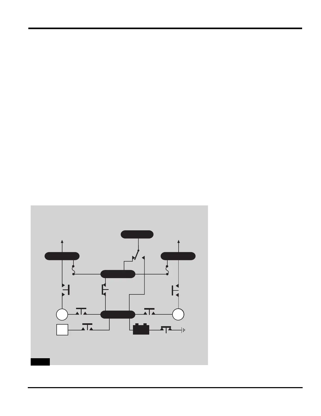
DC Relays
Refer to specific numbers in Figure
5C-12
for the DC relays.
Start Relays
Start relays correct power from the
battery bus to the starter generator.
To energize the left or right start
relay (1), press either engine start
button. Once the start relay closes,
power flows to the engine starter; the
starter begins turning. Power to
close the solenoid start relay comes
from the aft J box only when the bat-
tery switch is in BATT. Automatic
ignition sequencing takes place with
both engine ignition switches in
NORM.
A white light in each starter button
indicates closing of the start relay
contacts. The speed sensor in the
GCU removes power from the start
relay once the engine reaches
approximately 38% N
2
.
Emergency Power Relay
The two-way emergency power relay
(2) determines which source (battery
or generators) provides electrical
power to the Emergency bus. With
the battery switch in BATT or OFF,
the emergency power relay supplies
power from the Battery bus to the
Emergency bus. Placing the battery
switch in EMER energizes the relay
to carry power from the Hot Battery
bus to the Emergency bus.
Battery Relay
Positioning the battery switch to
BATT closes the battery relay (3) to
power the entire DC system. Posi-
tioning the battery switch to EMER
or OFF opens the battery relay.
BATTGPU
GEN GEN
BATTERY
DISCONNECT
RELAY
EXTERNAL
POWER
RELAY
START
RELAY
START
RELAY
POWER
RELAY
POWER
RELAY
LH MAIN
TO CB
PANELS
RH MAIN
TO CB
PANELS
BATTERY
RELAY
EMER
BATT
OR
OFF
EMERGENCY
POWER
RELAY
EMER
BATT BUS
HOT BATT
GEN
4
1
2
4
1
6
3
5