5B-64 Developed for Training Purposes Citation Bravo
September 2005
CAE SimuFlite
Symbol Generators
The symbol generators receive and
process aircraft sensor inputs from
the navigation receivers, gyros,
weather radar, and guidance sys-
tems, and transmit that data to the
PFDs in its system. If a malfunction
of a symbol generator occurs, rever-
sion is possible by the SG1/NORM/
SG2 switch on the MFD controller.
If SG1 is selected, the pilot's symbol
generator/IC-600 is driving all three
displays; selecting SG2 has the copi-
lot's symbol generator/IC-600 driv-
ing these displays. In these
situations, the MFD will be normal
and both PFDs will have the same
format. The MFD has no complete
symbol generator function of its own
and its symbol generator is therefore
not selectable. The MFD operates
from the pilot's IC-600.
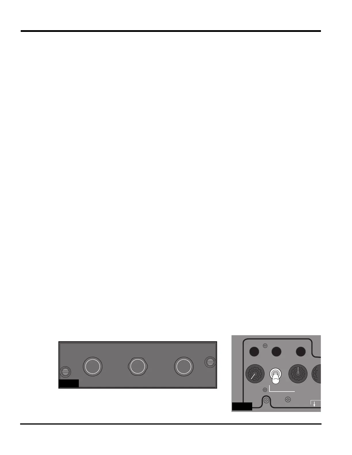
RI-553 Remote Instrument
Controller
The RI-553 Remote Instrument Con-
troller
(Figure 5B-48) selects the
course and heading for the displays.
The controls of the RI-553 are:
n
COURSE knobs - Set the VOR
navigation course. When the course
is set, the remote instrument con-
troller transmits course data to the
display controller, which in turn
transmits it to the IAC for the EFIS
and flight director function. The left
COURSE knob controls the pilot's
course selection; the right knob con-
trols the copilot's.
Some phases of instrument
controllers have knobs that are
either pulled or pushed to center
course or heading. Pressing or
pulling either the left or right
COURSE knob (PUSH DIR or
PULL DIR) centers that side's
course arrow display with a TO
flag on the EHSI display. The
display of ILS or FMS inhibits
this function.
n
HEADING knob - Sets the heading
bug on both EHSI displays. When
the heading bug is set, the symbol
generator transmits heading signals
through the flight director to the
IC-600. Pressing or pulling PUSH
SYNC or PULL SYNC synchro-
nizes the heading bug to the pres-
ent heading (lubber line).
Reversionary Functions
The reversionary functions retain
usable flight displays even after mul-
tiple failures, such as when the MID
displays data from a failed PFD or
when the remaining symbol genera-
tor replaces data from a failed sym-
bol generator.
The reversionary switches (see
Fig-
ure 5B-49)
control the following
heading, attitude, and air data rever-
sionary functions:
n
Pressing the ATT REV switch
selects the opposite side VG-14A as
an alternate attitude source and
annunciates an amber ATT 2 or ATT
1 on the EADI display of both PFDs.
PUSH
DIR
PUSH
SYNC
COURSE
PUSH
DIR
COURSEHEADING
5B-48
FLOOD LTS ON
ATT REV ADC REVHDG REV
OFF
OFF
LEFT
PANEL LIGH
CO
CEN
5B-49