5C-20 Developed for Training Purposes Citation Bravo
March 2009
CAE SimuFlite
Battery Start
A battery start, which is similar to a
GPU start, begins by checking the
voltmeter for a minimum battery
voltage of 24V. Switch positions are
as follows.
Both Generator Switches - GEN
Ignition Switches - NORM
Battery Switch - BATT
Boost Pump Switches - NORM or
OFF
With both generator switches on
GEN, the GCU can close the power
relay and bring the generator on-line
once generator voltage is equal to or
greater than Main bus voltage.
Either engine may be started first.
Because of the design of the Electri-
cal System and component loca-
tions, there is no electrical
consideration or advantage favoring
either engine to be started first.
Press the R ENGINE START button
momentarily. This action simultane-
ously accomplishes the following:
n
The right start relay closes; the
start button illuminates indicating
the start relay is closed.
n
The battery disable relay opens
and removes the ground from the
battery relay, which opens.
n
The engine instrument flood light
illuminates
n
The right fuel boost pump activates.
The FUEL BOOST R annunciator
illuminates, and the LO FUEL
PRESS R annunciator extinguishes.
n
The right engine ignition system
arms. The ignition light illuminates
when the throttle is moved to IDLE.
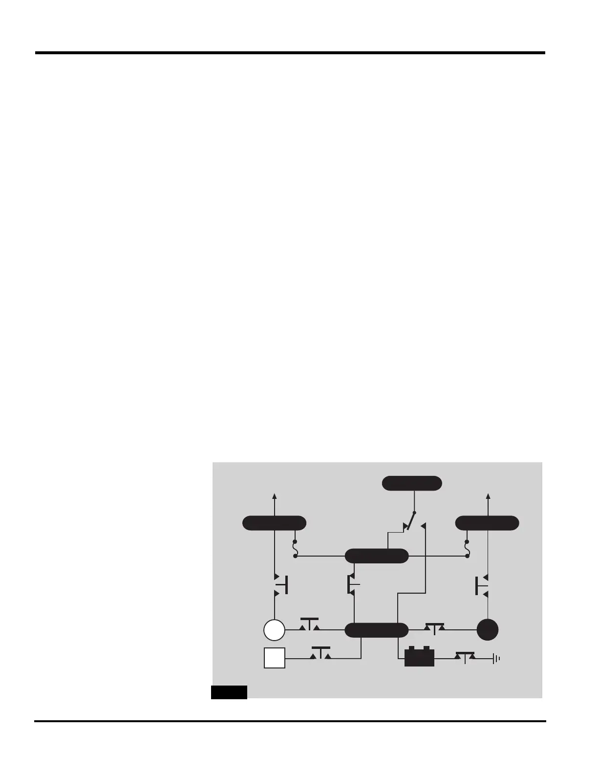
Power flows from the battery to the
Hot Battery bus and then to the right
starter/generator
(Figure 5C-15). The
GCU automatically terminates the
start sequence at approximately 39%
N
2
by disengaging the start relay.
Extinguishing of the FUEL BOOST R
annunciator, ignition light, engine
instrument floodlight, and the right
start button light confirms start
sequence termination.
The GEN OFF R annunciator extin-
guishes when the generator voltage
exceeds the battery voltage.
BATTGPU
GEN GEN
BATTERY
DISCONNECT
RELAY
EXTERNAL
POWER
RELAY
START
RELAY
START
RELAY
POWER
RELAY
POWER
RELAY
LH MAIN
TO CB
PANELS
RH MAIN
TO CB
PANELS
BATTERY
RELAY
EMER
BATT
OR
OFF
EMERGENCY
POWER
RELAY
EMER
BATT BUS
HOT BATT