Avionics
Citation Bravo Developed for Training Purposes 5B-17
September 2005
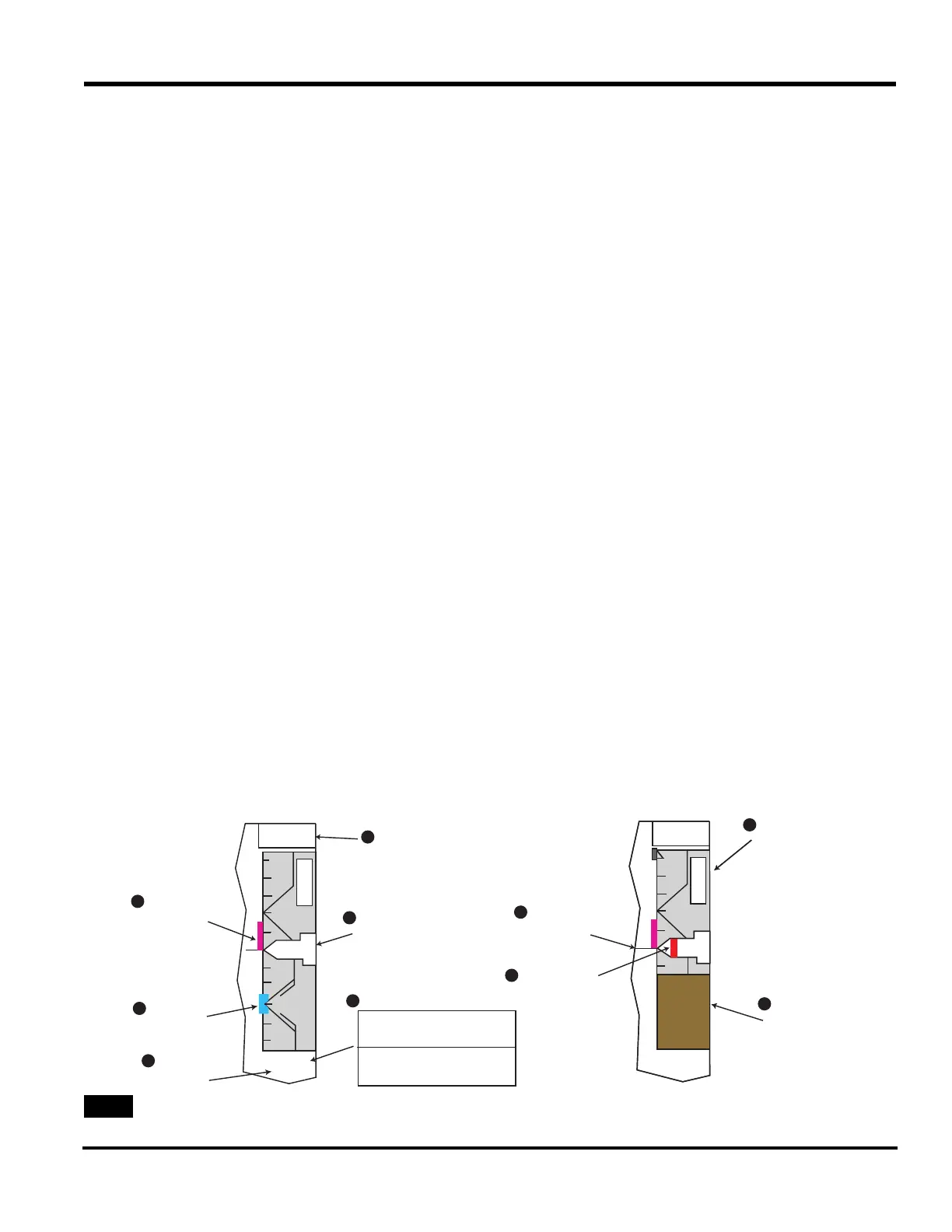
A description of the altitude/altime-
ter annunciations associated with the
altitude display follows. Refer to
specific numbers [(1) to (10)] in the
following discussion to locate these
annunciators on the Altitude Dis-
play, see
Figure 5B-11
Altitude Select Display
Data for the altitude select display
(1) is at the top of the altitude scale.
On power up, five cyan-colored
dashes appear. The data is set with
the ALTITUDE PRESELECT knob
on the lower right side of the MFD
bezel controller (see
Figure 5B-12).
Turning this knob one click synchro-
nizes the displayed altitude to the
current barometric altitude. The alti-
tude can be set from -1,000 to
60,000 ft in increments of 100 ft.
The set data is cyan colored.
When the aircraft is within the alti-
tude alert operating region, the set
data turns from cyan to amber. When
a departure from the selected altitude
occurs, the select display also
changes from cyan to amber.
The altitude alert operating region is
that area within 1,000 ft of the prese-
lected altitude during a capture
maneuver. At this time, the set data
turns amber. Once the aircraft is
within 200 ft of the preselected alti-
tude (250 ft for Phase I), the data
turns back to cyan. After capture, the
aircraft reenters the altitude alert
operating region if it departs more
than 200/250 ft from the selected
altitude. A momentary audio alert
sounds when the aircraft is 1,000 ft
from the preselected altitude or has
departed 200/250 ft from the select
altitude after capture. Five amber
dashes replace the display when alti-
tude preselect data goes invalid.
Metric Altitude Digital Display
and Barometric (BARO)
Altimeter Setting
A digital readout of the actual metric
altitude in meters (4) appears directly
below the barometric altitude setting
display. The metric value is available
only when hectopascals (hPa) is
selected as the reference for the baro-
metric altitude setting on the display
controller. The altitude data appears in
green with a white M tag. The data
range is from -305 to 18,290 m with a
resolution of 5 m. Amber dashes
replace the digital display when alti-
tude data goes invalid.
ALTITUDE
TREND VECTOR
AND SCALE
ALTITUDE
SELECT BUG
METRIC
ALTITUDE
DIGITAL
DISPLAY
ALTITUDE
SELECT DISPLAY
ALTITUDE
DISPLAY
BAROMETRIC
ALTIMETER SETTING
IN
HPA
INCHES
HECTOPASCALS
ALTITUDE
COMPARISON
MONITOR
ANNUNCIATOR
LOW ALTITUDE
AWARENESS
ALTIMETER
REFERENCE
LINE
BELOW 10000
FEET MARK
1
2
5
6
8
9
10
3
7
4
A
L
T
50
00
43
00
A
L
T
4500
50
00
43
00
A
L
T
14500
140
00
143
00
14000
29.92 IN
3047 M
29.92 IN
3047 M
Altitude Display Diagram