HELiOS Portables Technical Service Manual • PN 20562190 Rev E
41
HELiOS Portables
Troubleshooting & Repair Procedures
XI
RP12 – Pressure Hold Test
1. Attach a test pressure gauge (B-701732-00) to the top can-
nula barb on the front cover of the H300 or H850.
2. Set the flow control knob to a continuous flow setting (0.75
on the H300, C6 on the H850).
3. Attach the DISS nut and tailpiece of a HELiOS oxygen sup-
ply line (B-701656-SV) to a 0-6.90 bar (0-100 psi) source of
gaseous oxygen.
4. Insert the opposite end of the HELiOS oxygen supply line in
the quick connect.
5. Increase the gaseous oxygen source pressure until the test
pressure gauge reads 1.52 bar (22 psi) for the H300, or 1.65
bar (24 psi) for the H850.
6. Disconnect the HELiOS oxygen supply line from the quick
connect.
7. Allow the unit to sit undisturbed for 10 minutes.
8. Verify that the portable maintains a minimum pressure of
1.03 bar (15 psi) for the H300, or 1.24 bar (18 psi) for the
H850 at the end of the evaluation period.
9. If the pressure drops below this level, locate the leak by per-
forming the liquid leak detector test (RP2).
10. Disconnect the test pressure gauge.
NOTE: If you do not get a reading on the pressure gauge, reset
the demand valve as follows. Connect one tube of a dual-lumen
cannula to the bottom cannula barb and breathe in once or
twice.
NOTE: If unit was equipped without CPC fitting, remove kit
and reinstall tube in reverse order of RP27, then reinstall front
case.
NOTE: For newer units manufactured without the CPC
Connector, the CPC Connector Kit will need to be installed
first, refer to RP27, then reinstall the front case.
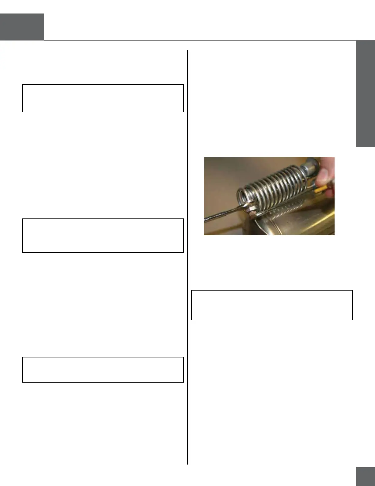
RP13A – Liquid Withdrawal Warming Coil R/R (H300)
1. Remove the covers (RP4).
2. Use an adjustable wrench to hold the R/E valve outlet arm
(with barbed fitting) stationary. Use a 7/16 inch open-end
wrench to remove the liquid withdrawal warming coil com-
pression nut from the R/E valve fitting.
3. Use a 5/16 inch open-end wrench to hold the fitting on the
stainless steel container tube stationary. Use a 7/16 inch
open-end wrench to remove the remaining liquid withdrawal
coil compression nut from the fitting.
4. Pull the ends of the warming coil from their fittings and re-
move the coil.
5. To reinstall the warming coil, reverse steps 1-4.
Figure 33: Compression Nut Removal
NOTE: Make sure to route the flexible urethane vent tube
through the inside of the warming coil positioned directly
below the vent valve.