S320 OCS Hardware User Guide
Page 25 of 46
3.3.1 Fiber Interface
The Fiber Interface is the optical interface for the S320 OCS. Input and output optical fibers are
connected to this interface. The Fiber Interface is configured at the factory for the connector
type and mode of operation specified by the user. As shown in Figure 4 and Figure 6, a standard
S320 OCS Fiber Interface has an array of 320 input and 320 output LC-UPC bulkhead connectors.
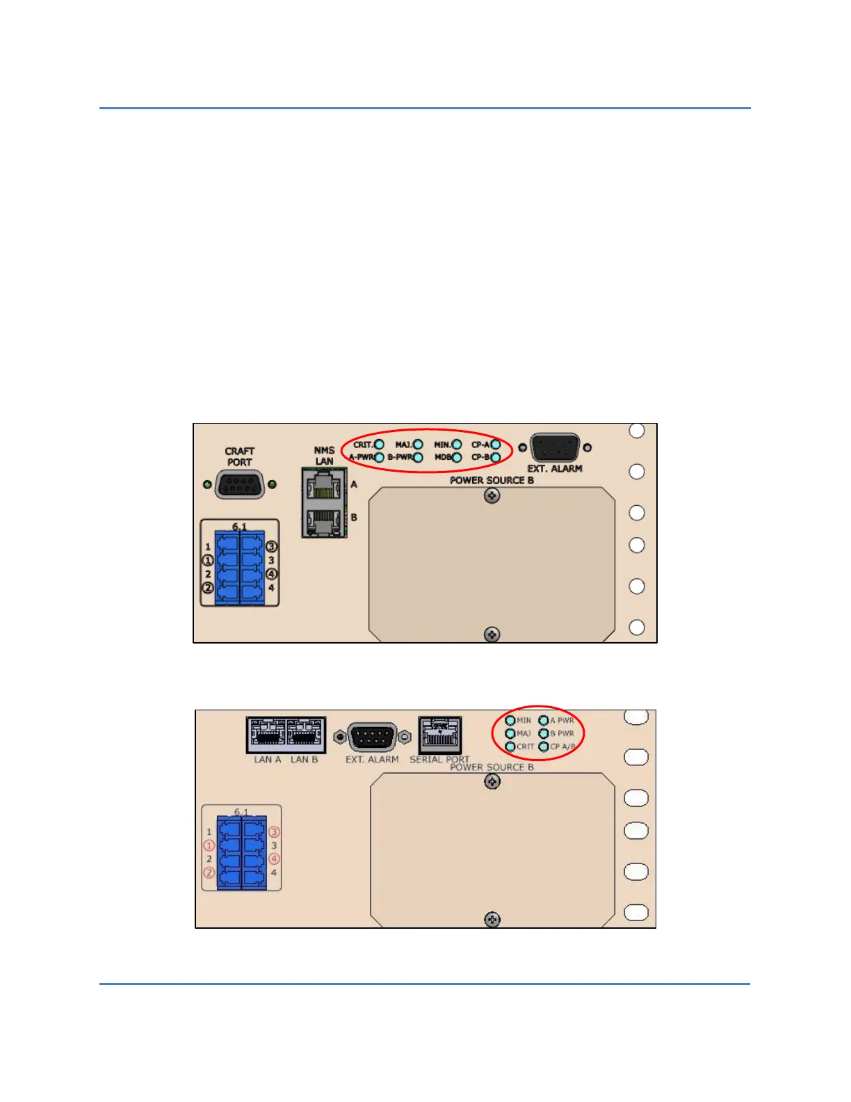
3.3.2 Operational Status LEDs
The operational status LEDs for both versions of the S320 OCS are located in the lower-right
corner of the front panel, just below the bulkhead connectors and above the Power Source B
power module bay (see Figure 4 and Figure 6). Eight (8) LED indicators on version 1 systems
(Figure 8), and six (6) LED indicators on version 2 systems (Figure 9), visually alert the user of
system-level fault conditions. These LEDs are summarized in Table 1 and Table 2.
Figure 8 – S320 OCS (Version 1) Front Panel (Close Up)
Figure 9 – S320 OCS (Version 2) Front Panel (Close Up)
 Loading...