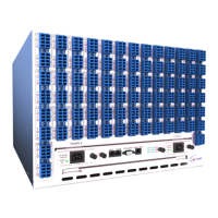
S320 OCS Hardware User Guide
Page 26 of 46
Table 1 – S320 OCS (Version 1) LED Indicators
One or more alarms (critical, major or
minor) are occurring.
The system is receiving power from
the indicated power source. Source A
is the primary power source; source B
is the backup power source.
The mirror driver board is operational.
The system has passed startup
diagnostics and is operating.
Table 2 – S320 OCS (Version 2) LED Indicators
One or more alarms (critical, major or
minor) are occurring.
The system is receiving power from
the indicated power source. Source A
is the primary power source; source B
is the backup power source.
If the LED is green, Control Processor A
(active CP) is controlling the system; if
the LED is amber, Control Processor B
(standby CP) is controlling the system.
Please refer to the CALIENT S320 OCS Troubleshooting and Alarm Reference Guide for detailed
information on S320 OCS alarm behavior.
3.3.3 External Alarm Interface
The S320 OCS external alarm interface is a DB9 connector located immediately to the right
of the LED status indicators on version 1 systems. On version 2 systems, the external alarm
interface is located to the left of the LED status indicators, between the Serial Port interface
and the LAN A/LAN B interfaces.

 Loading...