EasyManuals Logo

CALIENT S Series Hardware User's Guide

CALIENT S Series
46 pages
To Next Page IconTo Next Page
To Previous Page IconTo Previous Page
Page #37 background imageLoading...
Page #37 background image
S320 OCS Hardware User Guide
Doc. Part No. 460167-00
May 27, 2015
Rev. B7
Page 37 of 46
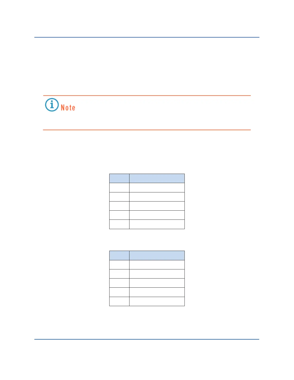
5.2.1.1 Serial Port Pinouts
Different cabling is used to connect to the serial interface on the S320 OCS, depending on which
version of the switch you have: version 1 or version 2. Version 1 uses a DB9 connector for the
serial interface and requires a USB-to-DB9 cable (Figure 13). Version 2 uses an RJ45 connector,
which requires a combination USB-to-DB9, RJ45-to-DB9 adapter cable (Figure 14).
Version 1 does not come with a serial cable; it must be provided by the customer.
Version 2 comes with the required combination serial cable.
Table 6 and Table 7 list the pinouts for the DB9 and RJ45 connectors used for the S320 OCS’s
serial interfaces.
Table 6 DB9 Serial Interface Pinout
Pin
Description
1
Request to send
3
Received data
4
Ground
5
Clear to send
6
Transmitted data
Table 7 RJ45 Serial Interface Pinout
Pin
Description
2
Transmitted data
3
Received data
5
Ground
7
Clear to send
8
Request to send

Table of Contents

Other manuals for CALIENT S Series

Questions and Answers:

Question and Answer IconNeed help?

Do you have a question about the CALIENT S Series and is the answer not in the manual?

CALIENT S Series Specifications

General IconGeneral
BrandCALIENT
ModelS Series
CategorySwitch
LanguageEnglish

Related product manuals