Chapter 3: System planning Site planning
Page 3-14
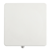
External 60º sector
antenna – 5 GHz AP
External 90º sector
antenna – 5 GHz AP
Table 48 PMP/PTP 450 wind loading (lb force)
Wind speed (miles per hour)
External 60º sector
antenna – 2.4 GHz
External 60º sector
antenna – 5 GHz AP
External 90º sector
antenna – 5 GHz AP
Drop cable grounding points
To estimate how many grounding kits are required for each drop cable, refer to the site installation diagrams
(Figure 27 , Figure 28 and Figure 29) and use the following criteria:
• The drop cable shield must be grounded near the ODU at the first point of contact between the drop cable
and the mast, tower or building.
• The drop cable shield must be grounded at the building entry point.
For mast or tower installations (Figure 27), use the following additional criteria:
• The drop cable shield must be grounded at the bottom of the tower, near the vertical to horizontal transition
point. This ground cable must be bonded to the tower or tower ground bus bar (TGB), if installed.
 Loading...