Chapter 2: System hardware System Components
Page 2-13
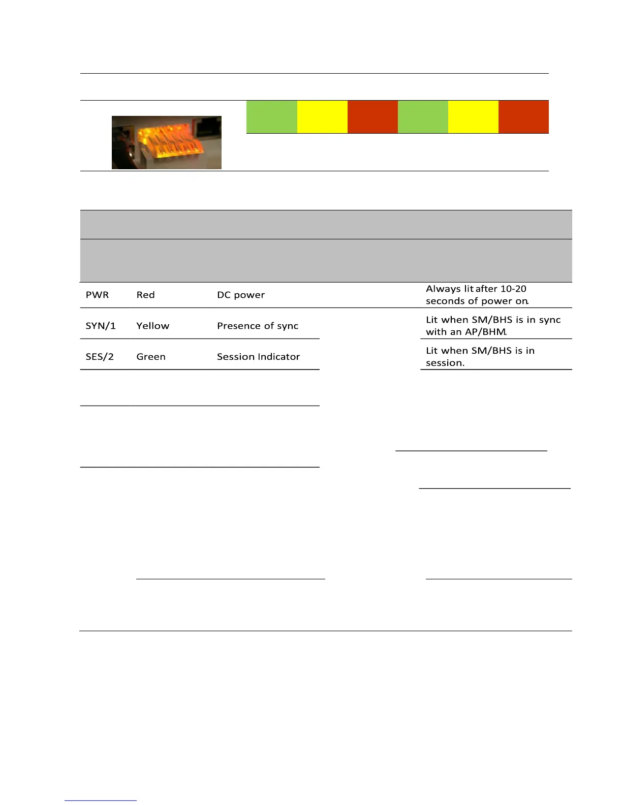
Table 15 SM/BHS LED descriptions
Status information provided
“Operating”Mode “Aiming” Mode
GPS/3 Red Unused
Presence of data
ACT/4 Yellow activity
on the Ethernet link
For PMP/PTP
450i
Red/ Green/
Ethernet link
Orange
LNK/5 (bi-colored for
10/100/1000)
On - high interference.
Blinking - medium These five
LEDs interference.
act as a bar graph
Off - low interference.
to indicate the
relative quality of Flashes during data transfer.
alignment. As Frequency of flash is not a power level
diagnostic
indication. improves during
alignment, more of
these LEDs are lit.
Continuously lit when link is
present. 10Base-T : Red
100Base-T : Green
1000Base-T : Orange
Continuously lit when link is
present.
Operating Mode
• Scanning: If the SM/BHS is not registered to AP/BHM, then these three LEDs cycle on and off from left to
right (SYN/1, SES/2 and GPS/3).
• Ethernet Link: The LNK/5 LED lit continuously when link is present.
 Loading...