PTP 550 QUICK START GUIDE
PAGE 7
Table 1 ODU rear interfaces
Port name Connector Interface Description
Main Ethernet RJ45 POE input 802.3at Power over Ethernet (POE).
100/1000BASE-T
Ethernet
Management and/or data.
SFP SFP Optical or Copper
Gigabit Ethernet
Management and/or data.
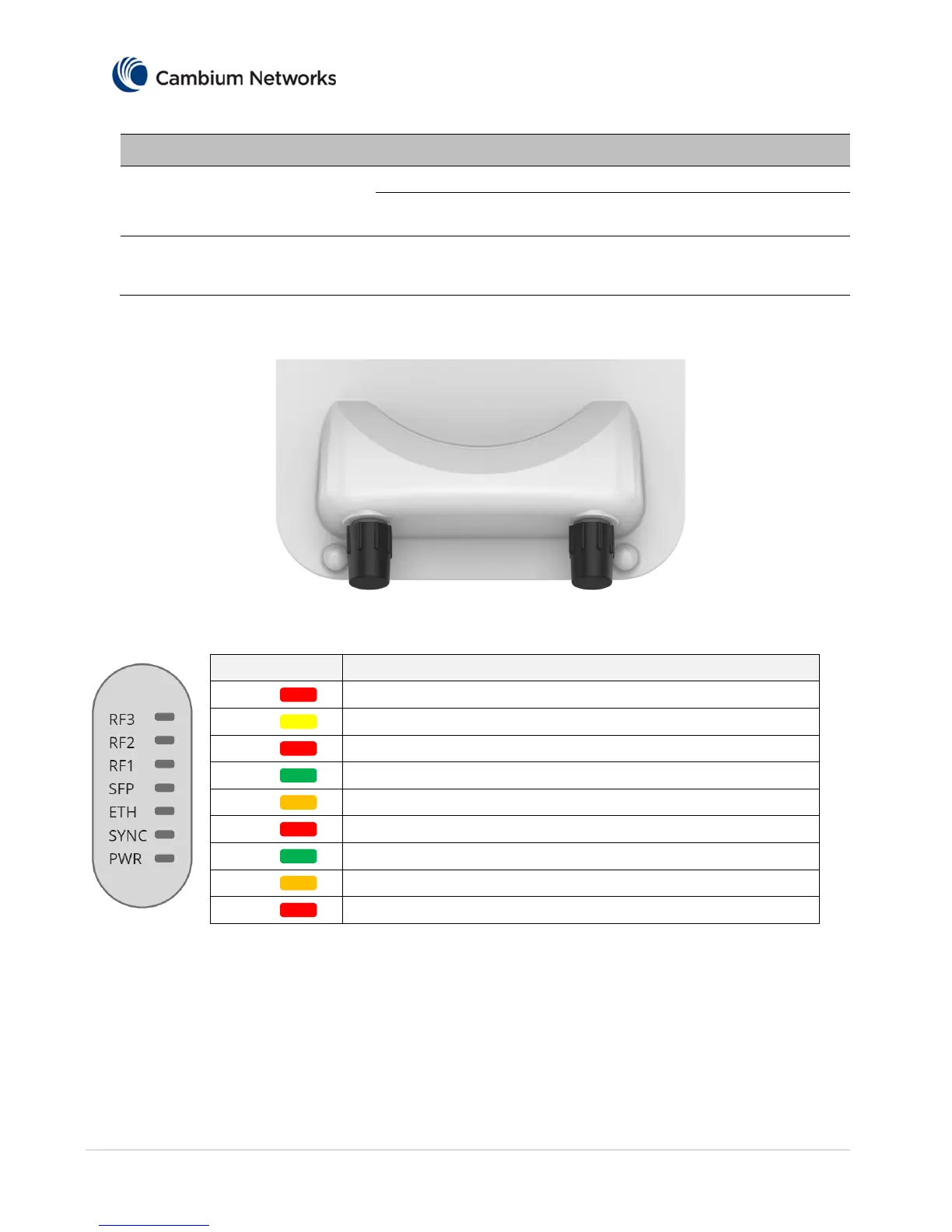
The front of the connectorized ODU provides N type female connectors for RF cable interfaces to
antennas with horizontal (H) and vertical (V) polarization.
LED Reference
PWR
PWR LED is “Red” -- PTP 550 is connected to a power source
SYNC
SYNC LED is “Yellow” -- PTP 550 is connected to a sync source
ETH
ETH LED is “Red” -- PTP 550 has a 10BASE-T link
ETH
ETH LED is “Green” -- PTP 550 has a 100BASE-T link
ETH
ETH LED is “Orange” -- PTP 550 has a 1000BASE-T link
SFP
SFP LED is “Red” -- PTP 550 has a 10BASE-T link
SFP
SFP LED is “Green” -- PTP 550 has a 100BASE-T link
SFP
SFP LED is “Orange” -- PTP 550 has a 1000BASE-T link
RF 1-3
RF 1, 2, & 3 indicate the RF signal strength
Power Supply Unit (PSU) description
The PSU is an indoor unit that is connected to the ODU and network terminating equipment using Cat5e
cable with RJ45 connectors. It is also plugged into an AC power supply so that it can inject Power over
Ethernet (POE) into the ODU.
 Loading...