EasyManua.ls Logo

Cambridge Audio 550A Service Manual

Cambridge Audio 550A
61 pages
To Next Page IconTo Next Page
Page #1 background imageLoading...
Page #1 background image
Gallery Court Hankey Place London SE1 4BB UK
Tel: +44 (0)20 7940 2200 Fax: +44 (0)20 7940 2233
550A/650A
Issue Date: 10
th
June 2009
________________________________________________________________________
SERVICE MANUAL
________________________________________________________________________
550A/650A
Power output: 550A
650A
60 watts (into 8)
75 watts (into 8)
THD (unweighted): 550A
650A
<0.002% @ 1kHz, 80% of rated power
<0.05% 20Hz - 20kHz, 80% of rated power
<0.02% 20Hz - 20kHz @ 10W
<0.002% @ 1kHz, 80% of rated power
<0.03% 20Hz - 20kHz, 80% of rated power
<0.02% 20Hz - 20kHz @ 10W
Frequency response (-1dB) 5Hz - 50kHz
S/N ratio (ref 1W) >92dB (unweighted)
Input impedances 47kohms
Power Amp damping factor >100
Max. power consumption: 550A
650A
500W
600W
Standby power consumption <1W @ rated mains
Bass/Treble controls
Shelving, ultimate boost/cut +/- 7.5dB @ 20Hz and
20kHz
Dimensions
120 x 430 x 350mm
(4.7 x 16.9 x 13.8”)
Weight: 550A
650A
8.0kg (17.6lbs)
8.4kg (18.5lbs)
Question and Answer IconNeed help?

Do you have a question about the Cambridge Audio 550A and is the answer not in the manual?

Cambridge Audio 550A Specifications

General IconGeneral
Input Impedance47k Ohms
Damping Factor> 100
Signal to Noise Ratio> 100 dB
Dimensions430 x 120 x 300mm (16.9 x 4.7 x 11.8")
Inputs4 x line level RCA
Power Output50 W per channel (into 8 ohms)

Summary

Product Specifications

Performance Metrics

Key performance metrics like power output, THD, frequency response, S/N ratio, and damping factor.

Physical Characteristics

Dimensions and weight of the Cambridge Audio 550A/650A amplifier.

User Interface and Controls

Front Panel Operation

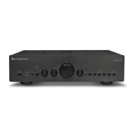
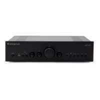
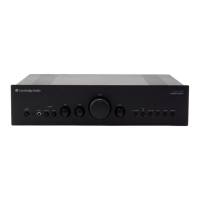
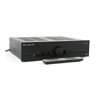
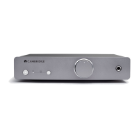
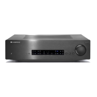
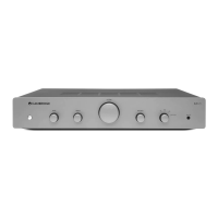
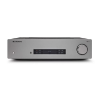
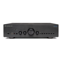
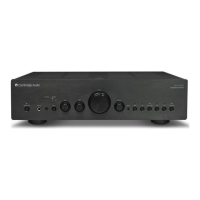
Description of front panel buttons, knobs, and indicators like Standby, Phones, and Volume.

Input Source Selection

Details on selecting audio sources such as MP3, CD, Tuner, DVD, Aux, and Tape Monitor.

Rear Panel Connections

Audio Output Terminals

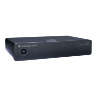
Loudspeaker terminals (A & B), Pre-Out sockets for external amplifiers or subwoofers.

System and Control Interfaces

AC power socket, IR emitter input, Control Bus, Tape In, and other connection ports.

Safety, Ventilation, and Placement

General Safety Guidelines

Crucial warnings and precautions for safe operation, handling, and maintenance.

Ventilation and Positioning Advice

Recommendations for optimal unit placement, airflow, and avoiding heat/moisture sources.

Compliance and Disposal

Information on product certifications (CE, FCC) and environmental disposal (WEEE).

Internal Circuitry and Components

Exploded Diagram and Parts List

Visual breakdown of amplifier internals and a detailed listing of all components.

PCB Schematics and Layouts

Circuit diagrams and physical component layouts for all PCBs.

Bill of Materials

Comprehensive lists of components for each PCB.

Set-up Procedure

Component Pin Configurations

Integrated Circuits (ICs)

Pinouts for various Integrated Circuits across different PCBs.

Transistors and Diodes

Pinouts for transistors and diodes used in the amplifier circuits.

Related product manuals