EasyManua.ls Logo

Cambridge Audio 640A Service Manual

Cambridge Audio 640A
41 pages
To Next Page IconTo Next Page
Page #1 background imageLoading...
Page #1 background image
Gallery Court Hankey Place London SE1 4BB UK
Tel: +44 (0)20 7940 2200 Fax: +44 (0)20 7940 2233
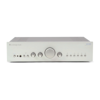
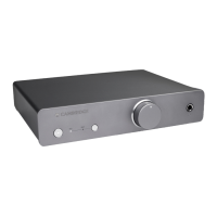
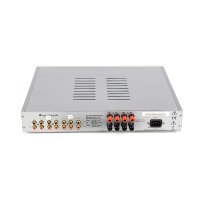
640A Integrated Amplifier
Issue Date: 16
th
December 2003 (Revised May 2008)
SERVICE MANUAL – AP14676/1
SPECIFICATIONS:
Power Output:
65 watts into 8 Ohms
100 watts into 4 Ohms
Input Impedance:
47k Ohms
Loudspeaker Impedance:
4 to 8 Ohms
Line:
380mV
Phono (using optional phono stage):
1.75mV
Total Harmonic Distortion (into 8 Ohms 80% rated power):
0.005% THD (No weighting) @ 1kHz
0.003% THD (A weighted) @ 1kHz
0.01% THD (No weighting) @ 20Hz - 20kHz
Frequency Response:
5Hz to 50kHz +/- 1dB
Bass:
+/- 10dB @100Hz
Treble:
+/- 10dB @10kHz
Signal to Noise Ratio (No weighting):
92dB
Slew rate (into 8 ohms):
40V/uS
Max. Power Consumption:
615 watts
Dimensions (mm):
430 x 320 x 100
Weight:
7 kg/15.4 lbs
Question and Answer IconNeed help?

Do you have a question about the Cambridge Audio 640A and is the answer not in the manual?

Cambridge Audio 640A Specifications

General IconGeneral
BrandCambridge Audio
Model640A
CategoryAmplifier
LanguageEnglish

Summary

640A Integrated Amplifier Specifications

Safety Precautions and Important Notes

General Safety and Servicing Advice

Essential safety warnings, handling precautions, and servicing guidelines for safe operation.

Amplifier Bias Adjustment Procedure

Bias Setting Steps for Channels

Step-by-step guide for adjusting amplifier bias using specific presets and measurements.

Input & Tone Circuit Schematics

Tone Control Circuit Diagram

Schematic detailing the tone control section of the Input & Tone PCB.

Input Select Circuit Diagram

Schematic illustrating the input selection logic of the Input & Tone PCB.

Input & Tone PCB Layouts

Front Panel Circuit Schematics

Front Panel Circuit Diagram

Schematic detailing the electronic components and connections of the front panel assembly.

Front Panel PCB Layouts

Power Amplifier Schematics

Power Supply Circuit Diagram

Schematic illustrating the power supply stage for the amplifier's power amp board.

Protection Circuit Diagram

Schematic detailing the amplifier's protection circuitry against faults like DC offset or short circuits.

Power Amplifier PCB Layouts

Speaker Output Circuit Schematics

Speaker Output PCB Layouts

Mains Input Circuit Schematics

Mains Input PCB Layouts

Integrated Circuit Pin Layouts

Revised Input Select PCB Schematic

Alternative Input Select PCB Schematic

Related product manuals