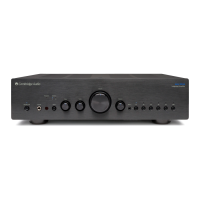
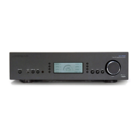
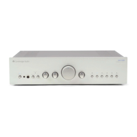
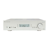
740A SERVICE MANUAL
TABLE OF CONTENTS
Safety Precautions & Important Notes 4
Exploded Diagrams
5-8
Exploded Diagram Parts List
9
Front Panel PCB Schematic (Tone Control)
10
Front Panel PCB Schematic (Microcontroller & LCD)
11
Front Panel PCB Layout (Top Side)
12
Front Panel PCB Layout (Bottom Side)
13
Front Panel PCB BOM
14-15
Preamp PCB Schematic (Tone Control)
16
Preamp PCB Schematic (Protection Circuitry)
17
Preamp PCB Schematic (Power Supply)
18
Preamp PCB Schematic (Headphone Driver)
19
Preamp PCB Schematic (Buffers & Switches)
20
Preamp PCB Board Layout (Top Side)
21
Preamp PCB Board Layout (Bottom Side)
22
Preamp PCB BOM
23-26
Amplifier Schematic (Speaker PCB)
27
Amplifier Schematic (Right Channel)
28
Amplifier Schematic (Left Channel)
29
Amplifier Schematic (Protection)
30
Amplifier Schematic (Power Supply)
31
Amplifier PCB Board Layout (Top Side)
32
Amplifier PCB Board Layout (Bottom Side)
33
Amplifier PCB BOM
34-36
Abus Schematic
37
Abus PCB Board Layout (Top Side)
38
Abus PCB Board Layout (Bottom Side)
39
Abus PCB BOM
40-41
Mains Schematic (Mains)
42
Mains PCB Board Layout (Top Side)
43
Mains PCB Board Layout (Bottom Side)
44
Mains PCB BOM
45
2
 Loading...