3
2
8
1
1
4
5
6
6
7
8
6
6
9
9
p. 5 - Manual FA01165 -EN - 05/2018 - © CAME S.p.A. - Translated original instructions
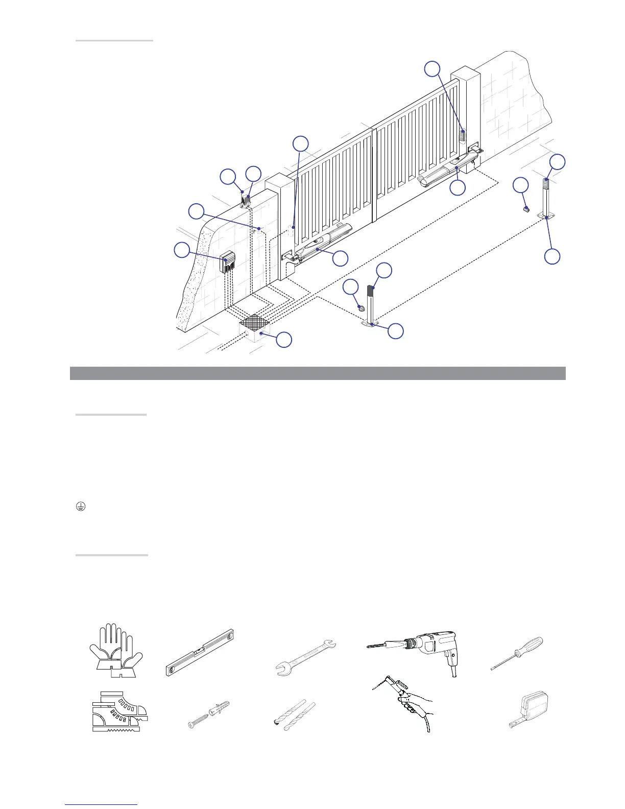
Standard installation
1.
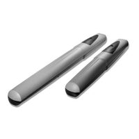
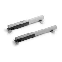
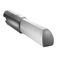
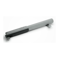
AXO
operator
2.
Control
panel
3.
Reception
antenna
4.
Flashing
light
5.
Selector
switch
6.
Photocells
7.
Electric cable junction box
8. Mechanical gate stops
9.
Photocell
column
GENERAL INSTALLATION INDICATIONS
⚠
Only skilled, qualified staff must install this product.
Pre
liminary checks
⚠
Before beginning, do the following:
• check that the gate structure is sturdy enough, the hinges work efficiently and that there is no friction between the fixed and moving parts;
• make sure that mea
surement C does not exceed the value shown in the reference table;• make sure you have fitted opening and c
losing
mechanical gate stops;
• make sure that the point where the gearmotor is fastened is protected from any impacts and that the anchoring surface is solid enough;
• make sure you have set up a suitable dual pole cut off device along the power supply that is compliant with the installation rules. It should
completely cut off the power supply according to category III surcharge conditions (that is, with minimum contact openings of 3 mm);
•
make sure that any connections inside the container (ones that ensure continuity to the protection circuit) are fitted with additional insulation
with respect to those of other electrical parts inside:
•set up suitable tubes and conduits for the electric cables to pass through, making sure they are protected from any mechanical damage.
T
ools and materials
Make sure you have all the tools and materials you will need for installing in total safety and in compliance with applicable r
egulations. The figure
shows some of the equipment installers will need.
 Loading...