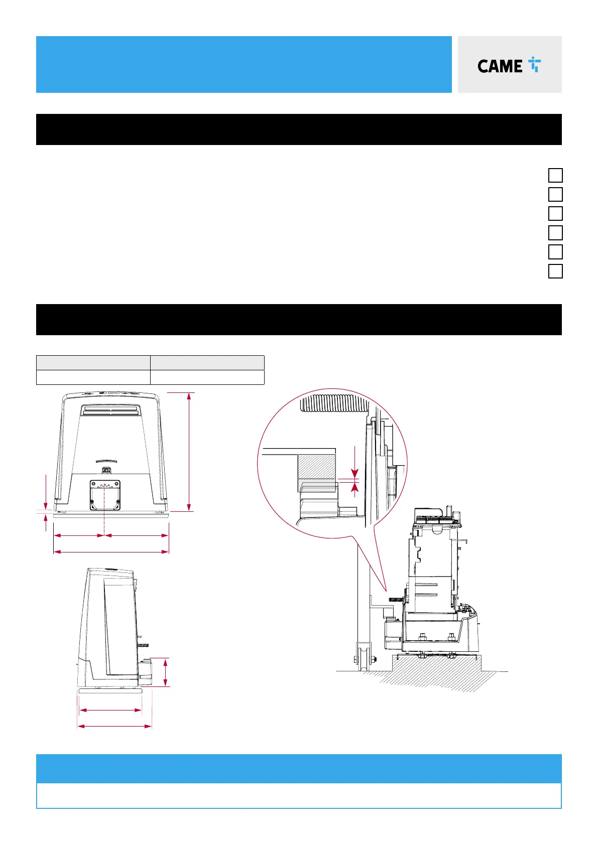
4 GEOMETRY
Max Leaf Length (m) Max Leaf Weight (kg)
20 2000
Preliminary checks
gate GEOMETRY
Tick
1. Ensure that all surfaces are perfectly level (Do not install on slopes)
2. Foundation frame dug out
3. Set up the corrugated tubes needed for the wiring coming out of the junction pit.
4. Use Ø 40 mm corrugated tubes to connect the gearmotor to the accessories
5. Prepare a Ø 20 mm tube to run the release cord through A.
6. Use Ø 40 mm corrugated tubes to connect the gearmotor to the accessories
The number of tubes depends on the type of system and the accessories that are going to be tted
INSTALLATION
Please refer to the full manual for installing the motor, rack and setting travel end points
1-2mm. The rack and pinion should mesh.
Do not allow the rack to rest on the pinion.
The gate motor must be installed parallel to the gate.
180
220
400
412
59
220
260