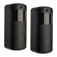
Example of a standard installation and relative
Dip Switch configuration
DBC 01(TX)
Does NOT
require
confi guration
DBC 04 Repeater
DBC 03 Repeater
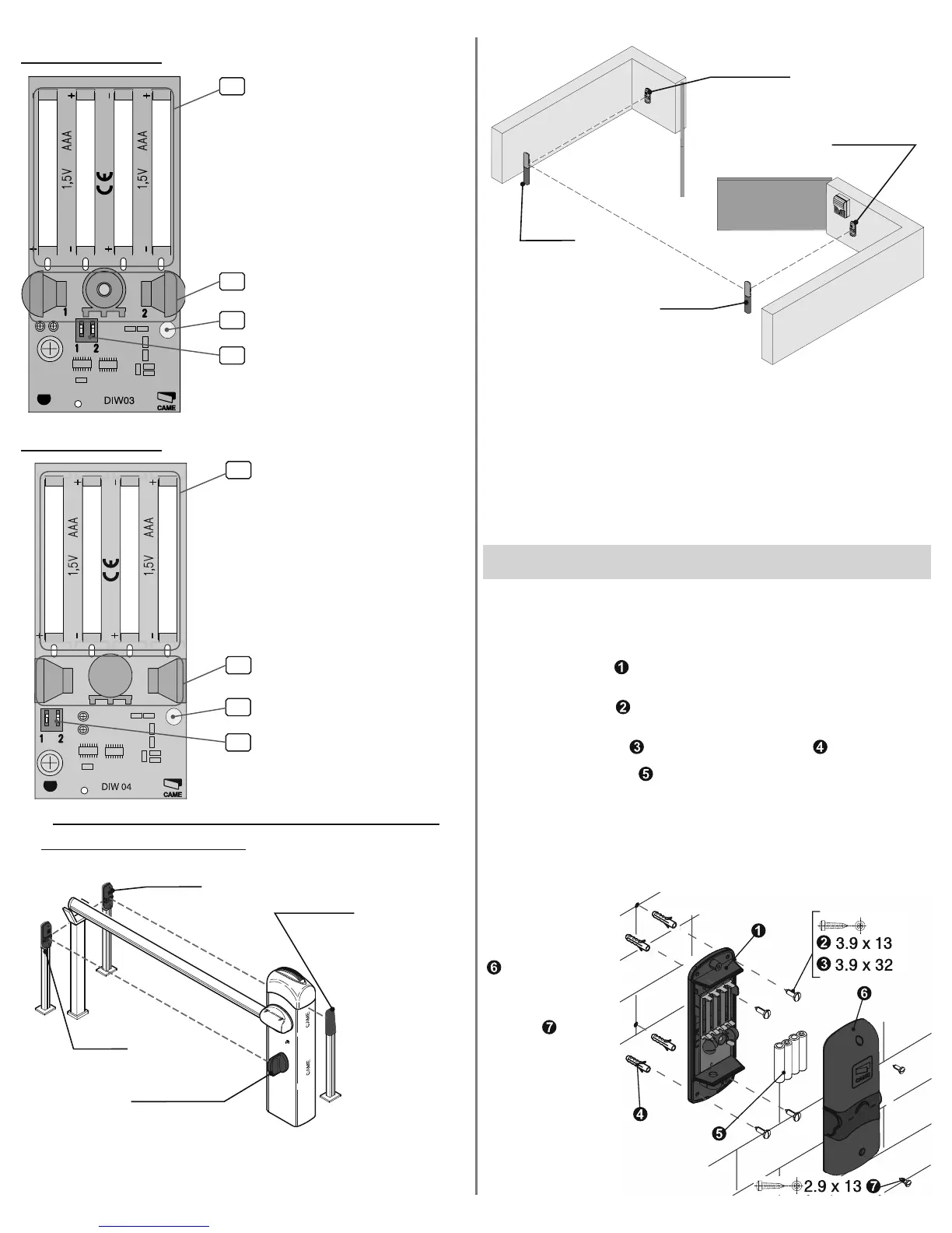
1-Battery housing
(Four 1.5V AAA batteries)
2-Infrared led,
selectable through the DIP
switch
3-Low battery warning led
4-Dip switch for selecting tran-
smission led
When Dip switch 1 ON, left-hand
led is active
When Dip switch 2 ON, right-
hand led is active
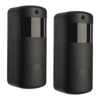
1-Battery housing
(Four 1.5V AAA batteries)
2-Infrared led,
selectable through the DIP
switch
3-Low battery warning led
4-Dip switch for selecting tran-
smission led
When Dip switch 1 ON, left-hand
led is active
When Dipswitch 2 ON, right-hand
led is active
+
2
1
1
2
4
3
DBC 01(RX)
Does NOT
require
confi guration
DBC 04
Dip 1 set to ON
Dip 2 set to OFF
DBC 03
Dip 1 set to OFF
Dip 2 set to ON
DBC 01(RX)
DBC 01(TX)
DBC 01(TX)*
DBC 01(RX)**
DBC 04*
DBC 03*
Note: When using DBC 01, DBC 03 and DBC 04, as explained
in the two preceding confi gurations, remember to remove
the bridge on DBC 01 (TX)
*With DB-L/DB-LN columns
**With G02802 photocell support
DBC 04*
DBC 03*
*With DB-L/DB-LN columns
DBC 01(TX)
Does NOT
require
confi guration
DBC 01(RX)
Does NOT
require
confi guration
DBC 04
Dip 1 set to ON
Dip 2 set to OFF
DBC 03
Dip 1 set to OFF
Dip 2 set to ON
• Verifi care Make sure that the distance between the two
photocells is not greater than 10 metres, and that they are
perfectly aligned, before installing.
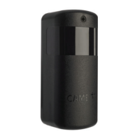
• Fix the bottoms of the photocells as follows:
- for the DB-L posts, use the UNI 6954 3.9x3 stainless
steel screws (found in the DB-L kit);
- for fi xing on the wall or on steel, use the UNI 6954
3.9x32 screws with the supplied nogs .
• Insert the batteries (you will need four 1.5V AAAs) into
the transmitter and the repeaters making sure the polarity
matches that shown on the card.
• Set the leds to (ON/OFF) depending on the make up of the
system. Connect the DBC01 (RX) as shown in the fi gure on
page 2.
• Close the
devices by
hooking the cover
at the top and
fi xing it in place
with the supplied
screws .
Assembly