-9-
T.C.A.
1 2
OG
T.C.A.
1 2
ROG
FUNZIONI
FUNCTIONS
FONCTIONS
FUNKTIONEN
FUNCIONES
REGOLAZIONI
SETTING
RÉGLAGES
EINSTELLUNGEN
REGULACIONES
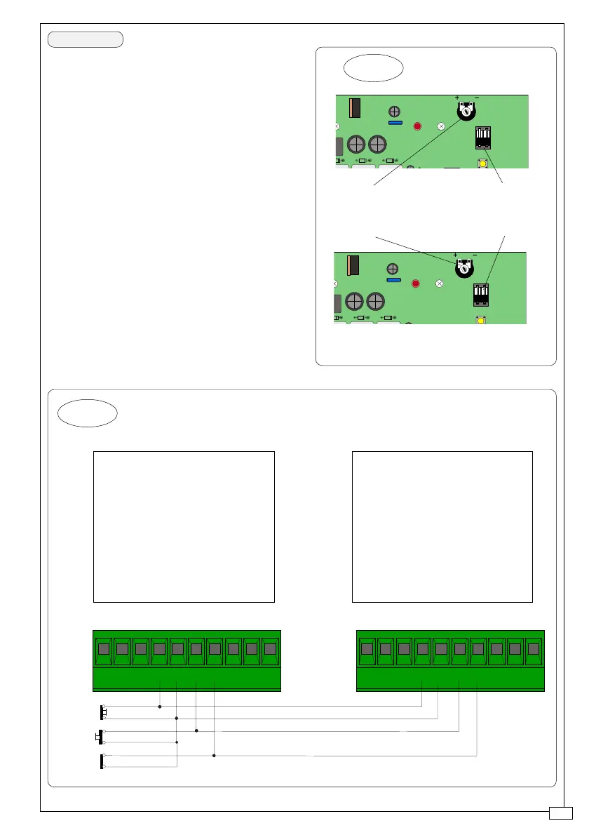
fig. 1
En el caso de instalación de dos
motores combinados, actúe de la
siguiente manera:
-Coordine el sentido de marcha de los
motorreductores "A" y "B", modificando
la rotación del motor «B»;
-Hay que realizar las mismas
regulaciones y funciones en ambos
cuadros (fig. 1);
-Realice las conexiones eléctricas entre
los tableros de borne del cuadro "A" y
"B", como indicado en la (Fig. 2);
Nota. En el caso de conexión
combinada, NO ESTÁ DISPUESTA LA
CONEXIÓN DE LA TARJETA DE
RADIOFRECUENCIA, por consiguiente
se excluye el empleo del radiocontrol.
ESPANOL
fig. 2
Morsettiera del quadro
motore «A»
Terminal board of the "A" motor
control panel
Plaque à bornes du tableau du
moteur «A»
Klemmbrett der Schalttafel vom
Motor «A»
Tablero de bornes del cuadro
motor «A»
Morsettiera del quadro
motore «B»
Terminal board of the "B" motor
control panel
Plaque à bornes du tableau du
moteur «B»
Klemmbrett der Schalttafel vom
Motor «B»
Tablero de bornes del cuadro
motor «B»
10 11 1 2 7 C1 FA FC FES 10 11 1 2 7 C1 FA FC FES
(1-2)
(2-7)
(2-C1)
 Loading...