Do you have a question about the CAME ZLJ24 and is the answer not in the manual?
Indicates sections for reading, safety notes, and user information.
Details the control panel's purpose for 24V DC automation systems.
Lists ISO certifications and compliance with relevant safety standards.
Describes the control panel's features, power, and safety mechanisms.
Provides technical drawings with dimensions for panel mounting.
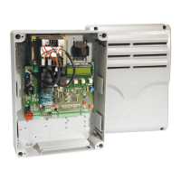
Lists and identifies all major components on the control board.
Ensures all conditions are met before starting installation.
Lists essential tools and materials for a safe installation.
Step-by-step guide for physically installing the control panel housing.
Details cable types and sections for power and signal connections.
Explains connections for powering accessories like lights and sensors.
Details wiring for flashing lights and courtesy lamps.
Explains how to connect various command inputs like buttons and key selectors.
Illustrates connections for different gearmotor types and encoders.
Describes how to connect and configure safety devices like photocells.
Details connections and settings for performing the photocell safety test.
Explains the function of each button for menu navigation.
Guides users through the menu structure to access settings.
Visual representation of the entire menu hierarchy and options.
Overview of primary navigation entries like Language, Functions, etc.
How to change the display language of the control panel.
Enables or disables the automatic closing function and sets its timer.
Configures gate operation using continuous button press.
Sets how the gate reacts to obstacles during movement.
Enables checking of safety device functionality.
Adjusts flashing light timing and ram thrust for electrolock release.
Stops gate operation and prevents auto-closing cycles.
Configures the CX input for various safety functions (C1-C4, C7-C8).
Configures the CY input for various safety functions (C1-C4, C7-C8).
Configures the CZ input for various safety functions (C1-C4, C7-C8).
Sets final closing thrust duration and electrolock release time.
Details settings for slow run, limit switches, and encoder configurations.
Sets endpoints to normally closed or open contacts.
Configures sequential/step-by-step and pedestrian opening modes.
Sets up courtesy, cycle, or flashing lights connected to 10-E.
Sets the output mode for B1-B2 terminals (Monostable/Bistable).
Adjusts number of motors, motor type, and operating speed.
Configures system for single/dual motors and specific motor models.
Adjusts the gate's speed percentage during operation.
Sets the deceleration speed percentage for gate movement.
Configures slow start and gearmotor sensitivity to obstacles.
Adjusts gearmotor sensitivity during operation with obstacles.
Sets gate leaf deceleration time before reaching endpoints.
Configures sensitivity for obstacle detection during operation and deceleration.
Adjusts obstacle detection sensitivity during different phases of gate movement.
Activates or deactivates slow run mode using encoder.
Sets opening and closing deceleration start points for M1 motor.
Sets M2 motor's opening deceleration start point.
Sets M2 motor's closing deceleration start point.
Sets points for motor deceleration before closing endpoint.
Sets points for motor deceleration before opening endpoint.
Calibrates gate's opening, closing runs, and decelerations using encoder.
Configures the automatic closing waiting time.
Sets waiting time for M2 leaf for automatic pedestrian closing.
Adjusts motor working time and M1's delayed opening.
Sets the waiting time for M2 leaf's delayed closing.
Adjusts flashing light time and electrolock release time.
Sets the gearmotor thrust time for closing and opening.
Sets the partial opening time for the M2 gate leaf.
Procedure for adding new users and changing existing user names.
Steps to modify the radio command code for a stored user.
Changes the command function associated with a user.
Procedures for removing individual or all registered users.
Saves user data to memory roll and restores it.
Loads saved user and setting data from the memory roll.
Shows software version, gate runs, and starting message.
Checks correct rotation direction of M1 and M2 gearmotors.
Instructions for installing radio receiver and coding cards.
Lists compatible transmitters for different frequencies and cards.
Step-by-step guide to add users, assign functions, and codes.
Procedure to change the name of an existing user.
Steps to modify the radio command code for a specific user.
Procedure to reassign functions to existing users.
Calibrates gate movement and deceleration points using encoder.
Lists common errors and guides for diagnosis and resolution.
Illustrates zones for normal speed, slowdown, and stop with encoder.
Recommendations for environmentally responsible disposal of components.
States compliance with essential EU directives for the device.
| Protection Rating | IP54 |
|---|---|
| Protection Degree | IP54 |
| Operating Temperature | -20°C to +55°C |
| Maximum Current | 0.5A |
| Motor Power Supply | 24V AC/DC |
| Power supply for accessories | 24V AC/DC |