2 06/2013 © CAME cancelli automatici s.p.a. -
The data and information reported in this installation manual are susceptible to change at any time and without obligation on CAME cancelli automatici s.p.a. to notify users.
ENGLISH
4.1 Dimensions, spans and anchoring holes
(mm)
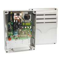
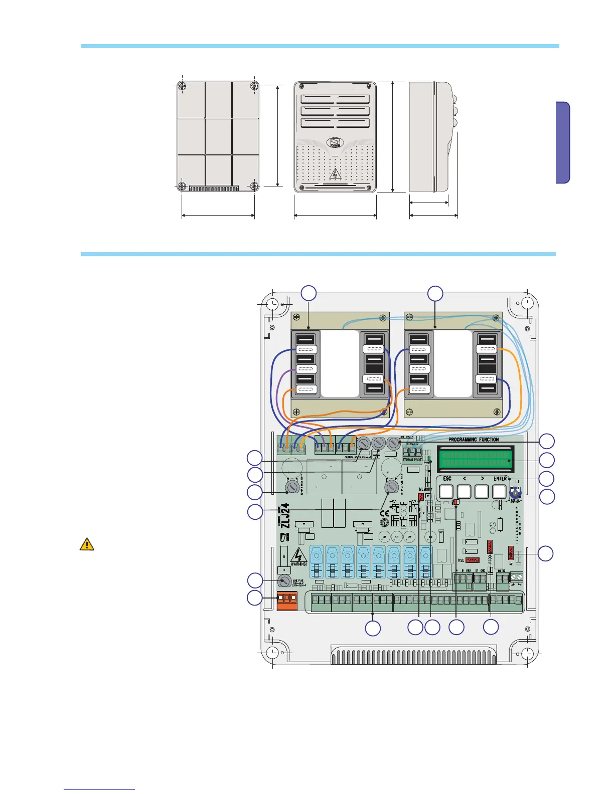
4.2 Main components
Warning! Before acting on the machinery,
cut off the main power supply and disconnect
any emergency batteries.
1 - Transformer
2 - Card fuse
3 - Accessories fuse
4 - Electrolock fuse
5 - Display
6 - Display lighting adjustment trimmer
7 - Memory roll card connector
8 - AF card connector
9 - R700 card connector
10 - Open contact error - warning LED
11 - Programming buttons
12 - Terminal board for connecting
13 - Terminal board for 230 V AC power grid
14 - Line fuse
15 - 230 V-power signalling LED
1
6 - Motor 1 fuse 1
17 - Motor 1 fuse 2

 Loading...