2 06/2013 © CAME cancelli automatici s.p.a. - The data and information reported in this installation manual are susceptible to change at any time and without obligation on CAME cancelli automatici s.p.a. to notify users.
ENGLISH
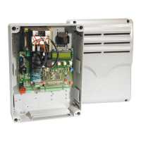
DF with DFI connections
monitor card
At each opening and closing command, the control board assesses the e ciency status of the control devices (photocells). Any
anomaly found is signalled with the fl ashing of the LED on the control panel. Consequently it cancels any commands coming from the
remote control or the button.
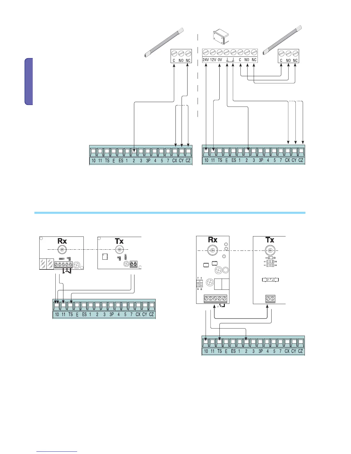
Electrical connection to enable the photocell safety test:
- the transmitter and the receiver, must be connected as per the diagram;
- from the functions menu, select “safety tests” and select either CX - CY - CZ input/s to activate the test
.
6.3 Electrical connection for running the photocell safety test
Confi gure either (N.C.) contacts CX, CY or CZ,
input for EN 12978 compliant safety devices
such as sensitive edges. See CX, CY or CZ input
functions in:
- C7 «Open while closing»,
During gate closing,
opening the contact causes inversion of movement
until gate is fully open;
- C8 «close while opening», During gate opening,
opening the contact causes inversion of movement
until gate is fully close.
- Deactivated, if contact is unused.

 Loading...