Do you have a question about the CAME ZL180 SERIES and is the answer not in the manual?
Explains the meaning of symbols used in the manual for important information and safety notices.
Defines the specific applications and purpose of the ZL180 control panel for swing gate operators.
Provides essential guidelines for cable selection and power limitations for proper application.
Details key technical specifications such as power supply, power consumption, insulation, and operating temperature.
Lists the types and ratings of fuses used for protection within the control panel.
Explains the connections for the transformer, listing color codes for wires.
Ensures essential pre-installation checks are performed for safety and proper setup.
Lists the necessary tools and materials required for a successful installation.
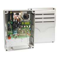
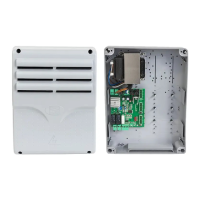
Provides instructions on how to securely fix and mount the control panel enclosure.
Details cable types and minimum thickness requirements for various connections according to length.
Describes the function and connection of indicator lights and signal flashers.
Explains how to connect power supply and accessories, including voltage and power limits.
Illustrates connection diagrams for A3024N-A5024N gearmotors, detailing wiring for different configurations.
Provides connection diagrams for F7024N gearmotors, detailing wiring for different configurations.
Explains the connection and activation of an electrical lock and the 'Ram Blow' function.
Details the connection and function of safety devices like photocells and sensitive edges.
Describes the connection and operation of command devices like stop buttons and key selectors.
Provides instructions for connecting photocells for functional testing and enabling the test operation.
Sets up control panel for specific gate operator models and leaf configurations using DIP switches.
Selects between opening slowdown or opening stop functionality using DIP switches.
Instructions for connecting the antenna to the radio receiver.
Details on how to install and recognize the radiofrequency card.
The CAME ZL180 is a control panel designed for 24V swing gate operators, specifically the F7024N, A3024N, and A5024N models. It operates on a 230V AC power supply at 50/60 Hz, providing 24V power to all command, control, and accessory devices. The panel is engineered and manufactured by CAME Cancelli Automatici s.p.a., adhering to current safety regulations and holding ISO 9001:2000 and ISO 14001 certifications.
The ZL180 control panel incorporates an amperometric device that continuously regulates the motor's drive coefficient. This sensor detects overcharges, such as when the gate encounters an obstacle, and immediately reverses the gate's direction. If the gate is closing, it reopens; if it is opening, it closes. A safety feature dictates that after three consecutive obstacle detections, the gate will stop in the open position, disabling the automatic closing function. To resume movement, a command button or remote control must be pressed.
The control panel offers several core functions:
The ZL180 supports various command modes:
The photocells can be configured to either reopen the gate when an obstacle is detected during closing or to initiate a partial stop.
The control panel also includes several adjustable options via trimmers:
Further implemented options include:
The ZL180 is designed for professional installers and qualified personnel. Proper installation involves ensuring the control panel's anchoring point is protected and solid, using appropriate bolts and screws. A suitable omnipolar cut-off device with contacts more than 3mm apart and an independent power supply is required. All internal connections providing continuity to the protective circuit must have extra insulation. Appropriate tubing and conduits are necessary for electrical cables to prevent mechanical damage.
The control panel's base is fixed in a protected area using round top Phillips recessed head screws. Pre-punched holes are provided for cable glands and corrugated tubing, with diameters of 23mm, 29mm, and 37mm. Pressure hinges are assembled to secure the cover.
The ZL180 can be calibrated for F7024N or A3024N gate leaves up to 3 meters. For A5024N models with leaves over 3 meters and to reduce peripheral speed, specific DIP switch settings and button presses are required to program the panel. The panel is set by default for two gearmotors. For single-gate leaf operation (M2 gearmotor), different DIP switch settings and button presses are used.
The microswitches on RA terminals are set by default for opening stop. To enable slowdown in opening, requiring compulsory setback mechanics, specific DIP switch settings and button presses are needed.
The ZL180 supports connecting a 12V (15W max) electric lock in two modes. One mode excludes the use of the second radio channel on B1-B2, while the other does not allow for an indicator lamp on 10-5. Both modes involve specific DIP switch configurations and a common programming procedure. The "ram blow" function can also be activated through DIP switch settings.
Safety devices such as photocells and sensitive edges can be connected to the "Partial stop" (N.C.) socket, which halts moving gate leaves and causes them to close automatically. The "Open during closing" (N.C.) socket is for safety devices that, when activated during closing, reverse the gate's motion until it is fully open.
Command devices include a stop button (N.C. socket) that halts the gate and excludes automatic closing, requiring a command button or transmitter press to resume. Key selectors and/or partial opening buttons (N.O. socket) allow for pedestrian passage. Key selectors and/or command buttons (N.O. socket) can also invert or halt gate movement depending on the selected function.
The control board performs a safety test of photocells with each opening and closing command. Anomalies are signaled by a flashing PROG LED, canceling remote control or button commands. To enable this test, the transmitter and receiver must be connected as per the diagram, and DIP switch 9 must be set to ON. Unused N.C. contacts should be excluded via DIP switches when this function is active.
All connections on the ZL180 are protected by quick fuses, which are easily replaceable. The manual provides a table detailing the fuse types for motors, the electronic board, accessories, and control devices.
The installation manual includes detailed instructions for adjusting the endstops for both ATI and FAST gearmotors. These adjustments are performed when the gearmotors are in release mode. For ATI gearmotors, the release key is inserted and turned clockwise. For FAST gearmotors, the release handle is turned counter-clockwise. The process involves manually positioning the gate leaf, releasing or detaching the endstop, sliding or repositioning it until the microswitch is activated, and then locking the assembly. For FAST gearmotors, the lower cam is rotated until the microswitch is activated, and then secured.
For left-hand gearmotors where the gate leaf measures less than 1.2m, the upper cam must be turned upside down before setting the microswitch. Similarly, for right-hand gearmotors, the opening endstop must be adjusted first, followed by the closing endstop.
The control panel features signal LEDs (ALIM, PROG, C1, C3, ST) that indicate the power status, remote control activation, and obstacle detection by photocells or activation of the total stop button. These LEDs aid in troubleshooting and verifying proper operation.
Activating the remote control involves connecting the antenna's RG58 cable to the terminals and locking the radiofrequency card into the electronic card. The radiofrequency card is only recognized when the power is on. Memorizing transmitter buttons involves pressing the CH1 or CH2 button on the electronic card until the LED flashes, then pressing the desired button on the transmitter until the LED stays on, indicating successful memorization.
The ZL180 is designed for longevity, with components made from recyclable materials such as aluminum, plastic, iron, and electrical cables, which are part of solid urban waste. Electronic cards, remote control batteries, and other components are considered hazardous waste and require specialized disposal by licensed firms.
| Operating temperature | -20°C to +55°C |
|---|---|
| Protection class | IP54 |
| Absorbed power in stand-by | 5 W |
| Power supply | 230 V AC (50/60 Hz) |
| Humidity | 95% (non-condensing) |
| Material | ABS |