Do you have a question about the CAME ZL22N and is the answer not in the manual?
This document provides comprehensive instructions for the installation, operation, and maintenance of the CAME ZL22N control panel, designed for 24 V UNIPARK parking saver barriers. It emphasizes safety precautions, technical data, and detailed procedures for both installers and end-users.
The manual begins with crucial safety instructions, highlighting that improper installation can lead to serious bodily harm. It stresses that the product should only be used for its specifically intended purpose, as any other use is hazardous. The manufacturer disclaims liability for damages resulting from improper, unreasonable, or erroneous use. The ZL22N control panel is designed for assembly into partly-completed machinery or equipment to create machinery compliant with Machinery Directive 2006/42/EC. The final installation must also adhere to this directive and applicable European standards. The manufacturer will not be liable for issues arising from the use of non-original products, which would also void the warranty.
All installation procedures, including cable laying, installation, and testing, must be performed by skilled, qualified technicians in full compliance with current regulations and state-of-the-art practices. It is imperative to cut off the mains power supply during all installation phases. Installers must verify that the operating temperature ranges of the device match those of the installation location. Before installation, the guided part of the barrier must be in good mechanical condition and operate correctly. The operator should be protected from direct water jets. The anchoring spot must be free from potential impacts, with solid anchoring surfaces, and suitable fasteners (e.g., screws and wall plugs) must be used. A dual-pole cut-off device, compliant with installation rules and capable of completely cutting off the power supply according to category III surcharge conditions, must be installed.
The installation site must be properly demarcated to prevent unauthorized access, especially by children and minors. Suitable protections must be implemented to prevent mechanical hazards for individuals within the operator's range. Electrical cables must pass through special pipes, ducts, and cable glands to ensure adequate protection against mechanical damage and must not touch parts that may overheat during use, such as the motor and transformer. All fixed controls must be clearly visible after installation, positioned where the guided part is directly visible but away from moving parts. Maintained action commands must be installed at a minimum height of 1.5 m from the ground and must not be accessible to the public. If not already present, a permanent tag describing how to use the manual release mechanism must be affixed near the mechanism. Before handing the system over to the end-user, installers must ensure that the operator is properly adjusted, and all safety and protection devices, including the manual release, are functioning correctly. The system must comply with harmonized standards and the essential requirements of Machinery Directive 2006/42/CE. Any residual risks must be clearly indicated with proper signage in visible areas and explained to end-users. The machine's ID plate must be fitted in plain sight upon completion of the installation. If the power-supply cable is damaged, it must be immediately replaced by the manufacturer, an authorized technical assistance center, or qualified staff to prevent risks. The manual should be kept in the technical folder along with manuals for all other devices in the automation system. End-users must receive all operating manuals for the final machinery.
The ZL22N is a control panel for a single Unipark barrier, expandable to control up to four Unipark barriers with three LM22N boards. Its functions are configured using DIP-switches. It supports multiple controls, allowing a single opening or closing command for multiple operators (from two to four simultaneously). With the ZL22N and LM22N control panel, multiple controls can only be wired (e.g., buttons, selectors). All connections and links are protected by rapid-fuses. The ZL22N control panel is specifically designed for controlling 24 V UNIPARK parking saver barriers. Any installation or use outside of this specified purpose is forbidden.
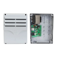
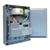
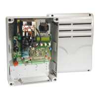
The control panel features several key components:
Before working on the control panel, the mains power supply must be cut off, and any batteries removed. The manual specifies minimum cable thicknesses for various connections based on cable length. For outdoor 230 V operation, H05RN-F-type cables (60245 IEC 57 compliant) are required, while indoors, H05VV-F-type cables (60227 IEC 53 compliant) are used. For power supplies up to 48 V, FROR 20-22 II-type cables (EN 50267-2-1 CEI compliant) are recommended. An RG58 cable up to 10 m long should be used for the antenna connection. If cable lengths differ from those specified, sections must be determined based on the actual power draw of connected devices and CEI EN 60204-1 regulations. For multiple, sequential loads, recalculations based on actual power draw and distances are necessary. For products not covered in this manual, refer to their accompanying literature.
To install the control panel:
The electrical connections include:
The control panel supports two operating modes:
To change the operating mode, switch on the board and hold down the programming button for 10 seconds. The red LED flashes twice for mode 1 to mode 2 transition, and once for mode 2 to mode 1. When the board is switched on, the red LED remains off in mode 1 and flashes twice in mode 2.
The terminal board for command and control devices (1 2 7 C1 TS) functions differently based on the operating mode:
Photocells: These provide an input for photocells or magnetic loops. During closing, if the contact opens, the barrier's movement inverts until it is fully open. If the safety device is not used, input 2 - C1 must be short-circuited.
Photocells safety test: With DIP-switch 3 set to ON, the control board performs a safety test at each opening and closing command to check the efficacy of safety devices. Any anomalies will inhibit all commands.
Amperometric sensor sensitivity adjustment: The motor current consumption is proportional to the parking saver power. The sensitivity can be adjusted using DIP-switches 1 and 2:
Functions:
Preliminary operations: Ensure the RG58 antenna cable is connected to the appropriate terminals and the AF board is inserted into the electronic board connector. Before fitting the AF board, the main power supply must be cut off, and any emergency batteries removed.
Adding a user:
Deleting a single user:
Deleting all users:
After completing electrical connections and powering up, fit the cover and secure it using the supplied screws.
Always comply with local laws for dismantling and disposing of the product. Packaging materials (cardboard, plastic) should be disposed of as solid household waste, separated for recycling. Other components (control boards, batteries, transmitters) may contain hazardous pollutants and must be disposed of by authorized, certified professional services. Dispose responsibly.
| Model | ZL22N |
|---|---|
| Category | Control Panel |
| Power supply | 230 V AC 50/60 Hz |
| Operating temperature | -10°C to +50°C |
| Protection class | IP54 |
| IP Rating | IP54 |