Do you have a question about the CAME ZL65 and is the answer not in the manual?
Guidance on responsible disposal of packaging materials.
Instructions for responsible disposal of product components and materials.
Detailed specifications including power, temperature, and duty cycle.
Information on line and accessory fuse types and ratings.
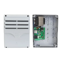
Steps for separating and drilling the control panel enclosure.
Instructions for drilling fixing points and mounting the control panel base.
Guidance on connecting wires and cables using cable glands.
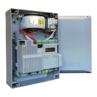
Procedure for connecting the control panel to the main power supply.
Details on the 24V AC/DC power output for connected accessories.
Information on the maximum power capacity for connected accessories.
Wiring diagrams for connecting gearmotors with encoders.
Function of the STOP button for gate control and exclusion.
Functions for partial, pedestrian, and open-only gate operations.
Functions for open-close, open-stop-close-stop operations.
Connection and function of a card reader.
Connection and function of a transponder selector switch.
Connection and function of a keypad selector.
Connection details for the antenna using RG58 cable.
Configuration for flashing beacon behavior during gate operation.
Configuration for additional lighting in the maneuvering area.
Configuration for a light indicating the operator's status.
Connection and power limits for a 12V AC electric lock.
Specification for a 6.8 Ohm, 7 Watt resistance.
Standard and safety test connections for DELTA photocells.
Standard and safety test connections for DIR/DELTA-S photocells.
Standard and safety test connections for DXR photocells.
Connection diagram for a DFWN sensitive edge.
Description of ESC, <>, and ENTER button functions for programming.
Initial steps and checks before starting the programming process.
Function F1 to stop the gate and exclude automatic closing.
Associating functions with the CX input.
Associating functions with the CY input.
Testing the operation of safety devices.
Enabling the hold-to-run mode for gate operation.
Associating commands with devices connected to 2-7.
Associating commands with devices connected to 2-3P.
Function for gate to remain idle upon obstacle detection.
Function to signal gate status or enable electric lock.
Managing operator slowdowns, obstacle detection, and sensitivity.
Setting a slowdown period after opening and closing commands.
Performing a closing thrust when limit-switches are reached.
Setting the type of control device connected.
Applying inward thrust before opening/closing to release electric lock.
Choosing the operating mode for the lighting device.
Setting the time for automatic closure activation.
Setting automatic closure time after partial/pedestrian opening.
Setting the duration for beacon activation before maneuvers.
Setting the gearmotor working time during opening and closing.
Adjusting the delay for M1 leaf opening relative to M2.
Adjusting the delay for M2 leaf closing relative to M1.
Adjusting the gearmotor closing thrust time.
Adjusting the electric lock release time.
Setting the gate travel speed as a percentage.
Setting the slowdown speed as a percentage.
Setting speed during travel self-learning.
Adjusting obstruction detection sensitivity during boom travel.
Adjusting obstruction detection sensitivity during slowdown.
Determining leaf partial opening percentage.
Setting M1 opening slowdown starting point.
Setting M1 closing slowdown starting point.
Setting M1 opening approach starting point.
Setting M1 closing approach starting point.
Setting M2 opening slowdown starting point.
Setting M2 closing slowdown starting point.
Setting M2 opening approach starting point.
Setting M2 closing approach starting point.
Setting the number of motors controlling the gate.
Enabling CRP operation for serial connection.
Saving user data, timings, and configurations to memory.
Uploading user data, timings, and configurations from memory.
Assigning a unique identification code (CRP address).
Setting the communication speed for the remote system.
Associating functions with wireless safety device RIO ED T1.
Associating functions with wireless safety device RIO ED T2.
Associating functions with wireless safety device RIO PH T1.
Associating functions with wireless safety device RIO PH T2.
Registering users and assigning functions.
Removing a registered user.
Removing all registered users.
Choosing the type of radio coding for transmitters.
Setting the type of gearmotor installed on M1 and M2.
Checking gate leaves direction and inverting motor phases if needed.
Starting the travel self-learning process.
Restoring factory settings, including travel calibration.
Viewing the number of operator manoeuvres.
Displaying the firmware version number of the control board.
| Brand | CAME |
|---|---|
| Model | ZL65 |
| Category | Control Panel |
| Language | English |