Do you have a question about the CAME zl92 and is the answer not in the manual?
Essential checks and obligations before installation.
Provides detailed specifications, features, and product size.
Overview of command devices, keypad, and transponder integration.
Information on photocells, safety edges, and input functions.
Overview of the function menu hierarchy.
Comprehensive list of programmable functions.
Setting motor type and verifying direction of travel.
Automatic calibration of gate movement and parameter reset.
Steps to activate and conduct motor tests.
Checking and correcting motor opening/closing phases.
Checks before calibration and safety during the process.
Detailed steps for the automatic gate run calibration.
List and explanation of error codes and system warnings.
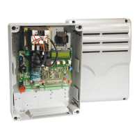
The CAME ZL92 is a sophisticated control panel designed for 24 V DC swing gate operators, specifically compatible with the STYLO, MYTO, FROG-J, and AMICO series. This unit is engineered and manufactured by CAME Cancelli Automatici S.p.A., ensuring adherence to high standards of quality and reliability.
The ZL92 control panel operates on a 230 V AC power supply with a frequency of 50/60 Hz. It manages all command devices and accessories, which function on 24 V. A key safety feature is the integrated transformer protection, which keeps the gate leaves open in the event of overheating, allowing them to close only once the temperature returns to a safe threshold. All connections are safeguarded by quick fuses, enhancing the system's overall safety.
The control panel's functionalities, including input and output contact management, time adjustments, and user management, are all handled via a clear display and managed by the internal software. This intuitive interface allows for easy configuration and monitoring of the gate's operations.
A notable feature of the ZL92 is its compatibility with the LB90 card, which enables the system to draw power from emergency batteries during power outages. These batteries are automatically triggered when the main power fails and are recharged once the line current is restored, ensuring continuous operation even in unforeseen circumstances.
The ZL92 offers a comprehensive range of programmable functions to customize gate operation. These include a "Total Stop" function (F1) to halt the gate and disable automatic closing, requiring manual intervention to resume movement. Safety contact inputs (CX and CY, F2 and F3) can be configured for various safety devices like photocells or sensitive edges, offering options such as re-opening during closing, re-closing during opening, partial stop, or stand-by obstacle detection. These inputs are compliant with EN 12978 standards, ensuring high safety levels. If unused, these contacts can be deactivated during programming.
A "Safety Test" function (F5) allows the control panel to check the efficiency of safety devices after every opening or closing command, signaling any anomalies with a flashing LED and canceling further commands from transmitters or buttons. The "Maintained action" function (F6) enables the gate to operate only when a button is continuously pressed, excluding other command devices like radio commands.
The control panel supports different command modes for gate operation (F7 and F8), including step-by-step, sequential, and partial opening for pedestrian access. An "Obstacle detection" function (F9) ensures that if a motor is stopped or a total stop command is issued, any movement caused by devices like photocells is prevented.
A "Warning light function" (F10) controls an indicator light that turns on when the gate is open. The "Exclude Encoder function" (F11) allows for the deactivation of the encoder, which is responsible for managing slow-downs and sensitivity. "Slow start" (F12) and "Closing thrust" (F13) functions provide control over the initial acceleration and final closing force of the gate, respectively.
The ZL92 supports various sensor types for operator commands (F14), including transponder or magnetic card readers with R700 encoder cards, or S7000 keyboards with R800 encoder cards. For specific gearmotors (Myto, Frog.J, Stylo-RME, Amico), "Ram head blow" (F16) and "Lock" (F17) functions are available to assist in releasing the electro-lock before opening and during closing/opening cycles, respectively.
The "10-E Light" output (F18) can be configured as a flashing light during gate operation, a courtesy light that stays on for an adjustable period, or a cycle light that remains on from the start of opening until the gate is fully closed.
Automatic closing times can be set for both full (F19) and partial/pedestrian (F20) openings, with adjustable waiting times. A "Pre-flashing time" (F21) allows the flashing light to activate for a preset interval before the gate starts moving. "Working time" (F22) defines the duration of motor operation during opening and closing.
Delay times for M1 and M2 gearmotors during opening (F23) and closing (F24) slow-downs can be adjusted, allowing for synchronized or staggered leaf movements. A "Courtesy light time" (F25) sets the duration the supplementary light stays on.
Motor speeds for M1 (F28) and M2 (F29) can be adjusted as a percentage of their maximum speed. Similarly, slow-down speeds for M1 (F30) and M2 (F31) are adjustable. An "Additional slow-down" function (F32) provides further speed reduction during closing for straight-arm Myto and Stylo gearmotors.
"Calibration speed" (F33) is dedicated to setting the motor speed during the gate calibration phase. "Gate run sensitivity" (F34) and "Slow-down sensitivity" (F35) adjust the obstacle detection sensitivity during normal runs and slow-downs, respectively. "Adjusting Partial Opening" (F36) allows for setting the M2 motor's opening percentage relative to the total gate run.
The ZL92 also allows for precise adjustment of slow-down points for M1 and M2 motors during both opening (F37, F41) and closing (F38, F42), calculated as a percentage of the full gate run. Similarly, the points at which M1 and M2 motors draw to fully open (F39, F43) or fully closed (F40, F44) positions can be configured. An "Additional closing slow-down point" (F45) can be set for straight-arm Myto and Stylo gearmotors.
The control panel can be configured for the number of connected motors (F46), either both M1 and M2, or only M2. Data can be saved to (F50) and loaded from (F51) a memory roll, provided it is inserted into the motherboard. The "User Menu" (U1, U2, U3) facilitates adding and canceling users with assigned commands, including step-by-step, sequential, open-only, pedestrian, or B1-B2 contact output commands. Finally, the "Info Menu" (H1) displays the software version.
Before any installation or adjustment, it is crucial to ensure the control panel is securely anchored to a solid, impact-protected surface, using appropriate fasteners. A suitable omnipolar cut-off device with contacts more than 3 mm apart and an independent power supply is required. Internal connections providing continuity to the protective circuit must have extra insulation. Proper conduits for electrical cables are essential to prevent mechanical damage.
The ZL92 emphasizes user safety through several features. Users are advised to keep the gate's operating area clear of obstacles and trim any interfering vegetation. Children should be prevented from playing with fixed command devices or remote controls. Regular checks for wear and tear on moving parts, components, securing points, and cables are recommended. Lubricating hinges and slide rails, and cleaning glass panels with a damp cloth (avoiding solvents), are part of routine maintenance.
In case of repairs or modifications, the operator must be released and not used until safety conditions are restored. Power supply must be cut off before manual openings. Users are strictly forbidden from performing any actions not explicitly instructed in the manuals. All repairs, modifications, and extraordinary maintenance must be carried out by qualified technical assistance staff. A periodic maintenance log should be kept to record all checks.
During operation, users should avoid working near hinges or moving parts and stay clear of the gate's area of operation. Resisting the gate's movement is dangerous. Awareness of dangerous points, indicated by pictograms or stripes, is important. When using "maintained action" commands, it is vital to ensure no one is in the operating area until the command is released. The gate may move unexpectedly, so always cut power when cleaning or performing maintenance.
The initial setup involves selecting the gearmotor type (A1), verifying the proper turning direction of the gearmotors (A2), and calibrating the gate run (A3). The "Motors test" (A2) allows checking if the gate leaf opens or closes correctly, with instructions to invert motor phases if needed. The "Gate run calibration" (A3) is an automatic procedure that determines the gate's full travel, during which all safety devices except "total stop" are disabled. It is crucial to ensure the movement area is free of obstacles and mechanical stops are in place before calibration. The system also includes a "Reset parameters" function (A4) to revert to default settings and cancel gate run calibration.
The ZL92 is designed for ease of maintenance and troubleshooting. The control panel provides error messages and warnings displayed on the interface, such as "Er1" and "Er2" for motor calibration interruptions, "Er3" for a broken encoder, "Er4" for safety device test errors, "Er5" for insufficient working time, "Er6" for maximum detected obstacles, "Er7" for transformer overheating, and "CO" or "C1/2/3/4/7/8" for unused or deactivated contacts. A flashing red LED indicates an uncalibrated command card.
CAME Cancelli Automatici S.p.A. operates an Environmental Management System certified to UNI EN ISO 14001, emphasizing environmental protection. Users are encouraged to follow disposal recommendations for packaging materials (cardboard, plastic), which are solid urban waste and recyclable. Product components, including aluminum, plastics, iron, and electrical wires, can be recycled. However, electrical boards and remote control batteries contain polluting substances and must be removed and given to qualified service companies for proper disposal.
The device complies with essential requirements of directives 2006/95/CE and 2014/30/UE, with an original declaration of conformity available upon request. These features ensure that the ZL92 is not only functional and safe but also environmentally responsible throughout its lifecycle.
| Model | ZL92 |
|---|---|
| Power supply | 230 V AC 50/60 Hz |
| Operating temperature | -20°C to +55°C |
| Protection class | IP54 |
| Protection Degree | IP54 |