26V
0V
17V
0
230V
16
1
9
15
4
17
7
5
13
11
12
2
14
10
6
8
3
P. 4 - Manual code: 319V21EN Vers. 3 04/2017 © CAME cancelli automatici S.p.A. - The data and information in this manual are subject to change at any time without prior notice required by Came Cancelli Automatici S.p.A.
ENGLISH
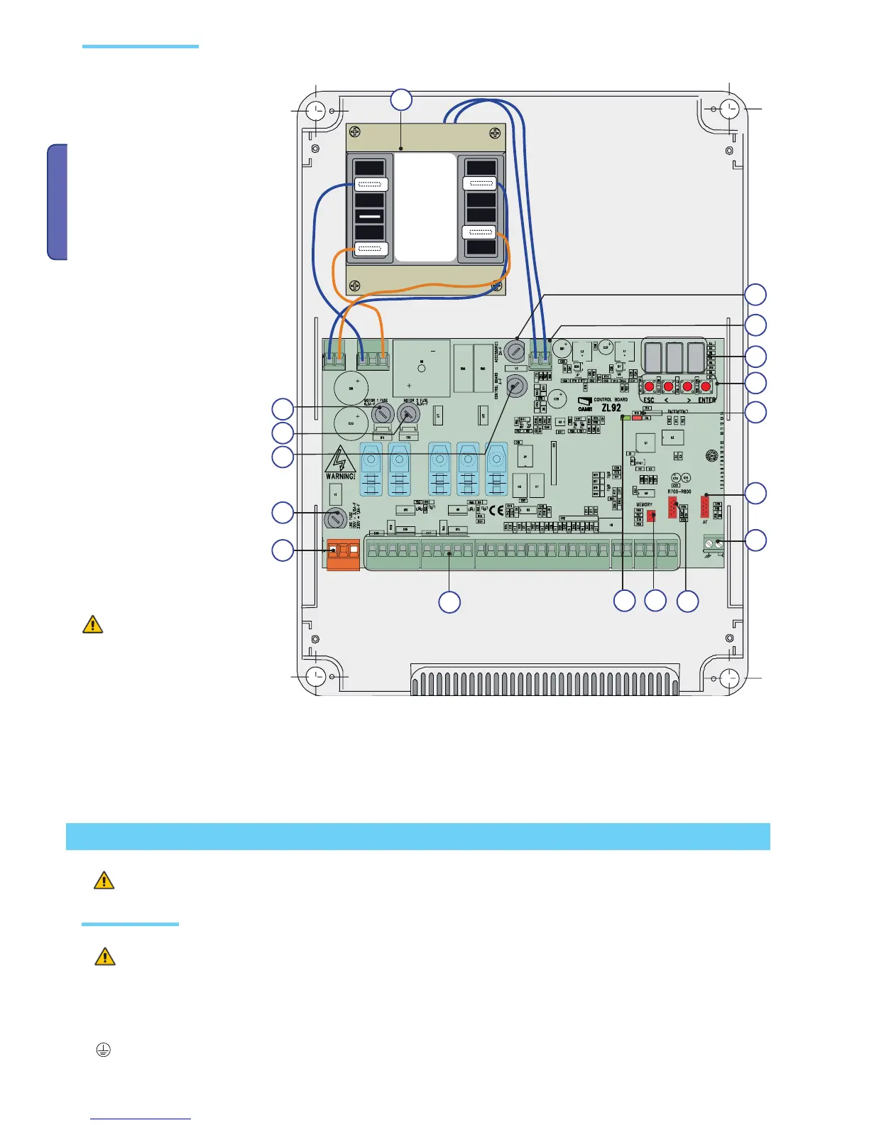
Main component parts
Before installing, do the following:
• Check that the control panel is anchored to a solid surface which is protected from possible impacts, and that the nuts, bolts,
wall plugs, etc., are suitable for the job.
• Make sure you have a suitable omnipolar cut-off device with contacts more than 3 mm apart, and independent (sectioned off)
power supply.
•
Make sure that any connections inside the box (that provide continuance to the protective circuit) are fitted with extra insulation
as compared to the other conductive parts inside.
• Set up proper pipes and conduits for electrical cables to pass through, making sure these are protected from mechanical damage.
Installation must be done by qualified, expert staff and in full compliance with current laws and regulations.
Installation
Preliminary checks
Warning! Before doing any work on
the control panel, make sure to cut
off the main current or disconnect
the batteries.
1 -Transformer
2 -Card fuse
3 -Accessories fuse
4 -Display
5 -Memory roll card connector
6 -AF card connector
7 -R700 or R800 card connector
8 -Lack of calibration warning LED
indicator
9 -Programming buttons
10 -Terminal boards
11 -230 V power terminal boards
12 -Line fuse
13 -Current on-line warning LED indicator
14 -Motor 1 fuse
15 -Motor 2 fuse
16 -Antenna connection terminal board
17 -Thermal terminal board

 Loading...