This document describes the ZLJ14 control panel, designed for 24 V gearmotors, and provides comprehensive instructions for its installation, programming, and maintenance.
Function Description
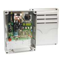
The ZLJ14 is a multi-function control panel for one-swing-leaf gates. It features a graphic programming and alert display, along with self-diagnosis capabilities for safety devices. All input and output contact functions, time settings, and user management are configured and viewed on the graphic display. The panel's wiring connections are protected by quick-fuses. It is specifically designed for integration into partly-completed machinery or equipment to form a complete system compliant with European Directive 2006/42/CE.
Important Technical Specifications
- Protection Rating (IP): 54
- Power Supply (V - 50/60 Hz): 230 AC
- Maximum Power of 24 V Accessories (W): 50
- Stand-by Consumption (W): 5
- Max. Power (W): 250 (overall power of connected motors)
- Operating Temperature (°C): -20 to +55
- Item: ABS
- Insulation Class: II
- Compatible Operators: AMICO, AXO, F4000, FAST, FERNI, FROG, FROG J, MYTO
Fuse Table
- Line (LINE-FUSE): 1.6 A-F
- Control Board (BOARD): 630 mA-F
- Accessories (ACCESSORIES): 2 A-F
- Motor (MOTOR): 10 A - 250 V Ø 6.3x22 UFG632310 (Spare parts code 119RIR316)
- Electric Lock (LOCK): 3.15 A-F
Cable Type and Minimum Section
| Connection |
Cable Length < 20 m |
Cable Length 20 < 30 m |
| Control panel power-supply |
3G x 1.5 mm² |
3G x 2.5 mm² |
| Motor power supply |
See operator manuals |
See operator manuals |
| Signaling devices |
2 x 0.5 mm² |
2 x 0.5 mm² |
| Command and control devices |
2 x 0.5 mm² |
2 x 0.5 mm² |
| Safety devices (photocells) |
2 x 0.5 mm² |
2 x 0.5 mm² |
For outdoor 230 V operation, H05RN-F-type cables (60245 IEC 57 compliant) are recommended. For indoor use, H05VV-F-type cables (60227 IEC 53 compliant) are suitable. For power supplies up to 48 V, FROR 20-22 II-type cables (EN 50267-2-1 compliant) can be used. Encoder connections require 2402C 22AWG-type cables up to 30 meters. CRP connections use UTP CAT5-type cables up to 1,000 m. Antenna connections require RG58 cable up to 10 m. Cable sections should be adjusted based on actual power draw and distances, especially for multiple, sequential loads.
Usage Features
The ZLJ14 offers extensive programming options via its graphic display and buttons (ESC, <, >, ENTER).
Programming Commands
- ENTER: Enters menus, confirms/memorizes values.
- ESC: Exits menus, cancels changes.
- < / >: Moves between items, increases/decreases values.
Key Programming Menus and Functions
- [LANGUAGE]: Selects interface language (Italiano, English, Français, Deutsch, Español, Portugues euro, Portugues bras).
- [FUNCTIONS] menu:
- [Auto Close]: Enables/disables automatic closing (0-300 s wait time). Disabled if safety devices trigger, after total stop, or power outage.
- [Maintained Action]: Enables/disables gate closing by continuous button press (contacts 2-3 for opening, 2-4 for closing). Excludes other control devices.
- [Obstruction Det.]: Enables/disables obstruction detection. Operator remains idle if safety devices detect an obstruction.
- [Safety Test] function: Enables/disables photocell functionality check after each command. Selectable photocell inputs (CX, CY, CZ).
- [Preflashing]: Enables/disables flashing light (connected to 10-E) before maneuver. Time set in [Preflash T] in [SET TIMES].
- [Jolt]: Enables/disables inward thrust before maneuver to release electro-lock. Time set in [Jolt time] in [SET TIMES].
- [Total Stop] function: Enables/disables total stop. Gate stops, automatic closing excluded, resumes with control device. Safety device on 1-2.
- [CX Input], [CY Input], [CZ Input]: Configures operating mode for connected devices (photocells, sensitive safety-edges). Options include:
- C1 Reopen during closing: Inverts movement until fully open.
- C2 Reclose during opening: Inverts movement until fully closed.
- C3 Partial stop: Stops gate, enables automatic closing.
- C4 Obstruction wait: Stops gate, resumes movement after obstruction removal.
- C7 Reopen during closing (sensitive safety-edges): Inverts movement until fully open.
- C8 Reclose during opening (sensitive safety-edges): Inverts movement until fully closed.
- [CI. Thrust]: Enables/disables closing thrust for a few seconds when leaf reaches limit-switch.
- [Lock]: Selects command for electric lock release (Close, Opening, Open-Close).
- [Lock Type]: Sets electric lock type (Impulsive, Continuous). Impulsive activates for a few seconds (time regulated by [Lock time]), Continuous activates during entire maneuver.
- [Config]: Configures opening and closing slow-downs. Options: [Timed LS], [Limit-switch], [SloDwn], [OpLs-Clslodwn], [ENCODER].
- [Limit switch]: Configures limit-switches as normally opened or closed contacts (N.C./N.O.).
- [Command 2-7] function: Configures contact 2-7 for step-step (open-close) or sequential (open-stop-close-stop) commands.
- [Light E]: Configures device connected to 10-E (Flash. light, Cycle). Cycle light stays lit from opening until fully closed (including auto-closing time).
- [Output B1-B2]: Configures contact B1-B2 as Monostable (button) or Bistable (switch).
- [SET GATE-SWING] menu:
- [Motor Type]: Sets operator model (FROG-F4024E, FROG-J, FROG-FL, AMICO, MYTO, AXO, FAST, FERNI, ATI).
- [Maneuver speed %]: Adjusts maneuvering speed (10%-100%).
- [Slow Down Spd. %]: Adjusts slow-down speed (10%-50%).
- [Soft Start]: Enables/disables slowed-down start after commands.
- [Amperom. Sens.]: Enables/disables amperometric sensitivity for obstruction detection.
- [Amperom Run]: Adjusts amperometric sensibility.
- [Slo.dwn. time] function: Sets leaf slow-down time before end stop (0-30 s).
- [ENCODER] menu:
- [Sensitivity]: Enables/disables obstruction detection sensitivity.
- [Swing Sens.]: Adjusts obstruction detection sensitivity during gate swing.
- [Slodwn. Sens.]: Adjusts obstruction detection sensitivity during slow-down.
- [Enc. Slwdwn.]: Enables/disables opening and closing slow-down starting points.
- [Op.Slo. %]: Sets opening slow-down starting point (1%-40% of complete swing).
- [CL. Slwdwn%]: Sets closing slow-down starting point (1%-40% of complete swing).
- [CL. Sftstp. %]: Sets latch-speed starting point before closing limit-switch (1%-15%).
- [OP. Sftstp.%]: Sets latch-speed starting point before opening limit-switch (1%-15%).
- [Calibrate Gate-Swing]: Automatic calibration of gate-leaf swing.
- [SET TIMES] menu:
- [A.C.T]: Automatic Closing Time (0-300 s).
- [Partial A.C.T.]: Automatic Closing Time for partial opening (0-300 s).
- [Working Time] function: Gearmotor working time during opening/closing (10-150 s).
- [Preflash T]: Preflashing time (1-60 s).
- [Lock time]: Electric lock release time (1-5 s).
- [Jolt time]: Jolt thrust time (1-3 s).
- [Part.open]: Time to define partial-opening space (5-60 s).
- [Court. Time]: Courtesy light lighting time (60-300 s).
- [USERS] menu:
- [New User]: Enters up to 250 users, associating a function (transmitter, swipe card, transponder).
- [Edit. name]: Changes user number or name.
- [Edit Code]: Modifies command code associated with a user.
- [Related Func]: Associates control function to saved device (2-7 step-step, Open only, 2-3P pedestrian/partial, B1-B2 contact output).
- [Remove Usr]: Modifies command code associated with a user.
- [Delete all Usr]: Removes all users.
- [Backup data]: Saves users and settings to memory roll.
- [Restore backup]: Uploads data from memory roll to electronic board.
- [INFO] menu:
- [Version]: Displays software version.
- [Number of Runs]: Displays number of completed maneuvers.
- [Open. Msg.]: Views/edits opening message.
- [Reset System]: Restores initial settings.
- [MOT TEST]: Checks proper rotation direction of gearmotor.
Warning and Lighting Devices
- Movement flashing light: Flashes during gate opening/closing.
- Cycle light: Outdoor light for additional driveway lighting. Configurable via [Light E] function.
- Courtesy light: Outdoor light for additional driveway lighting. Configurable via [Court. Time] function.
- Gate open warning light: Warns when gate is open, switches off when closed.
Maintenance Features
- Memory Roll Card: Used for saving user and system configuration data, which can then be transferred to another control board. It is recommended to remove the Memory Roll card during normal operation after saving data.
- Error Messages: The control panel provides error messages to assist with troubleshooting:
- [Encoder - ERROR], [Error!]: Broken encoder or wrong connection.
- [Safety test - ERROR]: Safety devices malfunctioning.
- [Limit-switch - ERROR]: Malfunctioning limit-switch contacts.
- [Operating Time - ERROR]: Insufficient operating time.
- [Safety - STOP], [C1], [C3], [C4], [C7] or [C8]: Malfunctioning safety devices or wrong connection.
- Graphic Diagram of Encoder's Functions: Illustrates the gate-leaf swing area, slow-down, and latch-speed points, tested for compliance with EN 12455 and EN 12453 impact force standards. This includes definitions for normal speed, reduced speed, encoder intervention zones, and various slow-down and latch-speed starting points.
- Fastening the Cover: After electrical connections and commissioning, the cover snaps into hinges and is secured with screws.
- Dismantling and Disposal: Compliance with local laws for dismantling and disposal is required. Packaging materials are recyclable. Other components (control boards, batteries, transmitters) may contain hazardous pollutants and must be disposed of by authorized, certified professionals.