p. 6 - Manual FA01082-EN - 02/2018 - © CAME S.p.A. - Translation of the original instructions
INSTALLATION
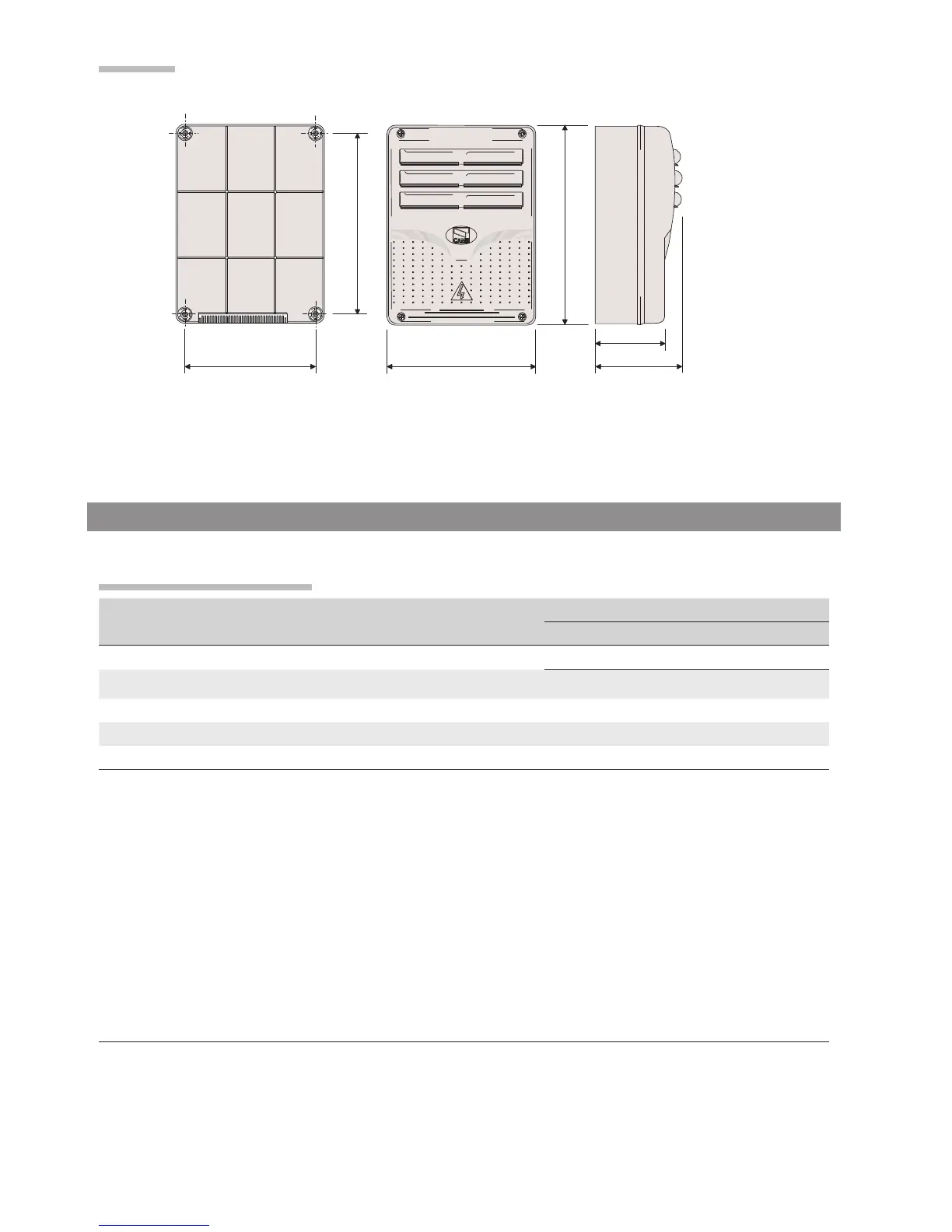
Dimensions
Cable type and minimum section
Connection
cable length
< 20 m 20 < 30 m
Control panel power-supply 3G x 1.5 mm
2
3G x 2.5 mm
2
Motor power supply see the corresponding operator-manuals
Signaling devices 2 x 0.5 mm2
Command and control devices 2 x 0.5 mm2
Safety devices (photocells) 2 x 0.5 mm2
& When operating at 230 V and outdoors, use H05RN-F-type cables that are 60245 IEC 57 (IEC)
compliant; whereas indoors, use H05VV-F-type cables that are 60227 IEC 53 (IEC) compliant. For power supplies up
to 48 V, you can use FROR 20-22 II-type cables that comply with EN 50267-2-1 (CEI).
For the Encoder use 2402C 22AWG-type cables up to 30 meters long.
To connect to the CRP, use UTP CAT5-type cables up to 1,000 m in length.
Use RG58 cable up to 10 m long to connect the antenna.
& If cable lengths differ from those specified in the table, establish the cable sections depending on the actual power
draw of the connected devices and according to the provisions of regulation CEI EN 60204-1.
&For multiple, sequential loads along the same line, the dimensions on the table need to be recalculated according
to the actual power draw and distances. For connecting products that are not contemplated in this manual, see the
literature accompanying said products

 Loading...