p. 12 - Manual FA01082-EN - 02/2018 - © CAME S.p.A. - Translation of the original instructions
& For saving transmitters, swipe cards or transmitters, see the [USERS] menu, any corresponding sub-menus and
details on the following pages.
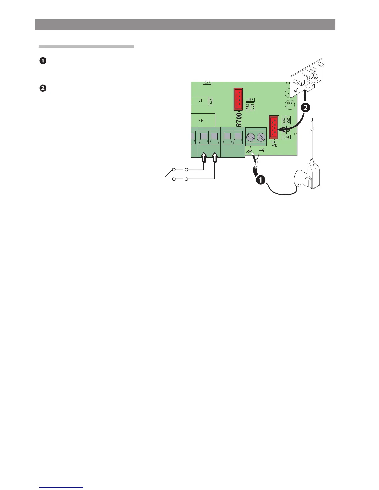
ENABLING THE RADIO CONTROL
Possible output of the second radio-receiver
channel (NO contact).
Contact rated for: 500 mA - 24 V DC.
Connect the RG58 antenna-cable to the corresponding
terminals.
Antenna and AF radiofrequency card
Fit the radio-frequency card into the slot on the control
board AFTER CUTTING OFF THE MAINS POWER SUPPLY.
N.B.: The control board recognizes the radiofrequency card
only when it is powered up.

 Loading...