1.2
04/2010
9 © CAME cancelli automatici s.p.a. -
The data and information reported in this installation manual are susceptible to change at any time and without obligation on CAME cancelli automatici s.p.a. to notify users.
ENGLISH
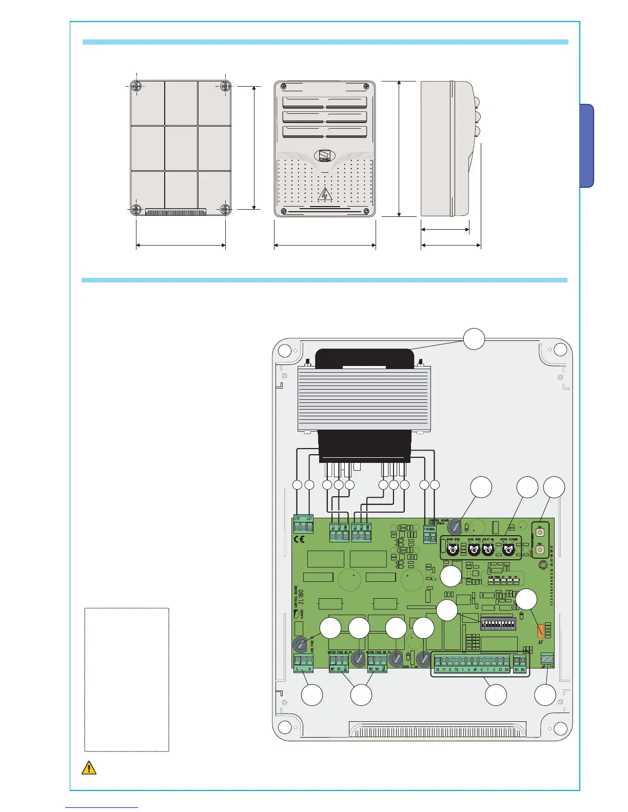
4.1 - DIMENSIONS, SPANS AND ANCHORING HOLES
4.2 - MAIN COMPONENTS
Warning! Before acting on the machinery, cut off the main power
supply and dis
connect any emergency batteries.
1 - Transformer
2
- Control unit fuse
3 - Trimmers (see page 9)
4 - Buttons for memorising the radio code
5 - Plug for the remote control frequency card
6 - Terminal board for connecting the antenna
7 - Terminal blocks for connecting accessories,
control and safety
8 - Terminal board for connecting the gearmotors
9 - Terminal board for 230 V AC power grid
10 - Line fuse
11 - M1 motor fuse
12 - M2 motor fuse
13 - Accessories fuse
14 - Fucntions selector
15 - Control and signalling LED unit
Black
White
Grey
Orange
Red
Blue
Brown
Yellow
Violet
LINKS
THE TRANSFORMER
 Loading...