2 06/2013 © CAME cancelli automatici s.p.a. -
The data and information reported in this installation manual are susceptible to change at any time and without obligation on CAME cancelli automatici s.p.a. to notify users.
ENGLISH
N.B.: If the cable length differs from that specified in the table, then you must determine the proper cable diameter based on the actual
power draw from the connected devices and according to the CEI EN 60204-1 standards.
For connections that require several, sequential loads, the sizes given on the table must be re-evaluated based on actual power draw
and distances.
When connecting products that are not specified in this manual, please follow the documentation provided with said products.
6.1 Cable and type and section
Connections
Type
of cable
Length of cable
1 < 10 m
Length of cable
10 < 20 m
Length of cable
20 < 30 m
Control panel power supply
FROR CEI
20-22
CEI EN
50267-2-1
3G x 1,5 mm
2
3G x 1,5 mm
2
3G x 2,5 mm
2
Power to motor with encoder * 3G x 1,5 mm
2
3G x 1,5 mm
2
3G x 2,5 mm
2
Power to motor** 2G x 1,5 mm
2
2G x 1,5 mm
2
2G x 2,5 mm
2
flashing lamp 2 x 1,5 mm
2
2 x 1,5 mm
2
2 x 1,5 mm
2
Transmitter photocells 2 x 0,5 mm
2
2 x 0.5 mm
2
2 x 0,5 mm
2
Receiver photocells 4 x 0,5 mm
2
4 x 0,5 mm
2
4 x 0,5 mm
2
Power supply to accessories 2 x 0,5 mm
2
2 x 0,5 mm
2
2 x 1 mm
2
Limit switch connection *** 3 x 0,5 mm
2
3 x 0,5 mm
2
3 x 0,5 mm
2
Control and safety devices 2 x 0,5 mm
2
2 x 0,5 mm
2
2 x 0,5 mm
2
Encoder connection **** TWISTATO max. 30 m
Antenna connection RG58 max. 10 m
6 Electrical connections
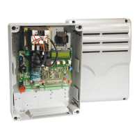
6) After the adjustments and settings, fix the cover
using the provided screws.
5) Snap the cover into place onto the hinges.
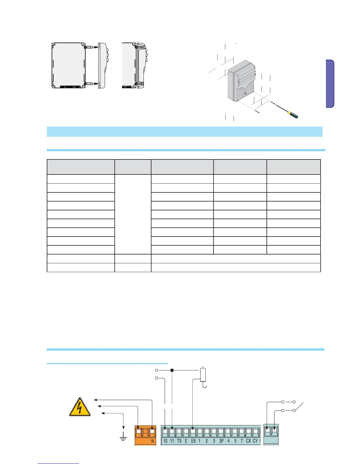
Terminals for powering the following accessories:
- 24 V AC.,DC Overall power allowed: 50 W
Power supply to accessories
Power supply
230 V AC 50/60 Hz
Electrolock
connection (12 V -
15 W max)
Possible output of the
radio receiver’s second
channel (N.O. socket).
Socket rating: 500 mA-24 V DC.
6.2 Electrical connections

 Loading...