Do you have a question about the CAME ZA3P and is the answer not in the manual?
Crucial safety warnings for installation and use, emphasizing potential for serious damage if instructions are not followed.
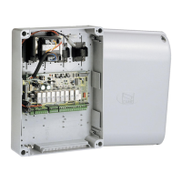
Details the multi-feature control panel for swing gates, its functions, and features.
Specifies panel usage for particular operators and its maximum power limit (600W).
Presents technical data (IP rating, power, temp.) and a fuse table for protection components.
Lists and labels all components on the control board, including the transformer and connectors.
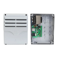
Provides the external dimensions of the control panel enclosure in millimeters.
Outlines requirements for skilled installers, power disconnection, and initial checks before starting installation.
Details required cable types and minimum cross-sections for various connections based on length.
Lists essential tools and materials needed for safe and compliant installation of the control panel.
Step-by-step instructions for securely mounting the control panel base and routing cables.
Details electrical connections for the main power supply, electrolock, and 24 VAC accessories.
Illustrates different CAME gearmotor models and their standard connection schemes for opening operations.
Describes the function and connection points for gate open warning, flashing lights, and courtesy lights.
Details the connections for various command devices like stop buttons, key-switches, and selectors.
Explains connections for safety devices (photocells, edges) and the safety test function.
Details how to configure operating modes using Selector A and Selector B DIP switches.
Guides on adjusting working time, auto-closing time, delayed closing, and slow-down speed via trimmers.
Instructions on how to adjust the motor torque by moving the faston to different positions.
Steps for connecting the antenna's RG58 cable and fitting the AF radiofrequency card to the control board.
Procedure for memorizing transmitters on Channel 1 (CH1) for commands and Channel 2 (CH2) for accessories.
Instructions to simultaneously press CH1 and CH2 to clear all memorized radio control transmitters.
Guide for fastening the cover after connections and provides instructions for product dismantling and disposal.
States that the product conforms to essential requirements of EU directives 2006/95/CE and 2014/30/UE.
| Motor power supply | 230 V AC |
|---|---|
| Maximum power | 800 W |
| Protection rating | IP54 |
| Operating temperature | -20°C to +55°C |
| Power supply | 230V AC ±10%, 50/60Hz |
| Functions | Automatic closing |