EasyManua.ls Logo

CAME ZT4 User Manual

CAME ZT4
36 pages
To Next Page IconTo Next Page
Page #1 background imageLoading...
Page #1 background image
Documentazione
Tecnica
S12
rev. 2.5
03/2004
©CAME
CANCELLI
AUTOMATICI
319S12
SERIE Z |
Z SERIES
| SÉRIE Z |
BAUREIHE Z |
SERIE Z
ZT4
CANCELLI AUTOMATICI
QUADRO COMANDO
ELECTRIC CONTROL PANEL
ARMOIRE DE COMMANDE
SCHALTTAFEL
CUADRO DE MANDO
CARATTERISTICHE GENERALI
ITALIANOITALIANO
ITALIANOITALIANO
ITALIANO
Descrizione quadro comando
Quadro elettrico per motoriduttori con
alimentazione 230V monofase/trifase
o 400V trifase; frequenza 50÷60 Hz.
Progettato e costruito interamente
dalla CAME Cancelli Automatici S.p.A.,
risponde alle vigenti norme di
sicurezza, con grado di protezione
IP54. Scatola in ABS, dotata di presa
per il riciclo d'aria. Garantito 24 mesi
salvo manomissioni.
Il circuito va alimentato sui morsetti R, S
e T (con alimentazione a 400V trifase)
oppure solo sui morsetti R e S
(con alimentazione a 230V monofase o
trifase ), protetto in ingresso con fusibili
da 8A. Il quadro comando ZT4 è
predisposto per l'alimentazione a 400V.
Nel caso di alimentazione a 230V
spostare il collegamento che
cortocircuita i morsetti «380» e «COM»
sui morsetti «220» e«COM»
(vedi pag.12).
240 mm
120 mm
145 mm
320 mm
Question and Answer IconNeed help?

Do you have a question about the CAME ZT4 and is the answer not in the manual?

CAME ZT4 Specifications

General IconGeneral
BrandCAME
ModelZT4
CategoryControl Panel
LanguageEnglish

Summary

General Characteristics

Description of control panel

Overview of the control panel's features and build.

Safety

Photocells for Re-opening (2-C1)

Re-opening during closing cycle via photocells.

Photocells for Re-closing (2-CX)

Re-closing during opening cycle via photocells.

Partial Stop

Gate shutdown with automatic closing activation.

Total Stop (1-2)

Gate shutdown without automatic closing.

Obstacle Presence Detection

System response to detected obstacles for safety.

Safety Test Function

Procedure to verify safety device functionality.

Accessories which can be connected

Other functions

Automatic closing

Automatic gate closing timer and its behavior.

Partial opening

Gate opening for pedestrian passage with auto-close adjustment.

Cycle lamp

Operation of the maneuvering zone illumination lamp.

Courtesy Light

Operation of the courtesy light for the maneuvering zone.

Maintained action function

Gate operation via continuous pushbutton press.

Pre-flashing

Pre-opening/closing light signal for 5 seconds.

Master function

Panel assumes control for paired motors.

Slave function

Panel exclusively controlled by the MASTER unit.

Enabling functions of partial stop or reclosure

Enabling partial stop or re-closing functions via dip-switch.

Type of command

Configuration of control modes (open-close, etc.).

Adjustments

Trimmer T.C.A. = Adjusts automatic closing time

Adjustment range for automatic closing time.

Trimmer AP.PARZ. = Adjusts partial opening

Adjustment range for partial opening time.

Main Components

Terminal block for external connections

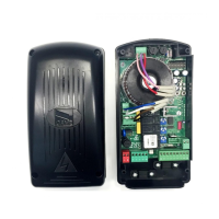
Connection point for external devices and wiring.

8A line fuse

Primary fuse protecting the main power input.

2A accessories fuse

Fuse protecting low-voltage accessories.

Socket AF radiofrequency board

Slot for inserting the radiofrequency receiver card.

Radio-code save buttons

Buttons for programming radio transmitters.

"Function selection" Dip-switch

Switches for configuring operational functions.

Trimmer AP.PARZ.: Partial opening adjustment

Adjustment for partial opening time.

Trimmer TCA: automatic closing time adjustment

Adjustment for automatic closing time.

Radio-code LED

LED indicator for radio code status.

Photocell Function Test

Electrical connection for safety-test functioning

Wiring instructions for performing the safety test.

Electrical Connections

Function Selection (Dip-Switches 1-10)

Automatic closing enabled

Activates the automatic closing function.

Open-stop-close-stop function

Configures the gate to open, stop, close, stop sequence.

Open-close function

Configures the gate to open and close sequence.

Only opening function

Configures the gate for opening only commands.

Maintained action operation

Gate operation requiring continuous pushbutton press.

Pre-flashing enabled

Activates a 5-second flashing light before movement.

Obstacle detection device enabled

Activates the obstacle detection safety feature.

Re-opening in closing phase enabled

Enables re-opening when closing is interrupted.

Re-closing while opening enabled

Enables re-closing when opening is interrupted.

Partial stop function enabled

Enables gate to stop partially during movement.

Total stop function enabled

Enables complete gate stop, disabling auto-closing.

Function Selection (Dip-Switches 11-20)

"Slave" function disabled

Disables the slave function for coupled connections.

Partial opening function (fixed 8s auto-close)

Partial opening with fixed 8-second automatic closing.

Partial opening function (adjustable auto-close)

Partial opening with adjustable automatic closing time.

Safety test function enabled

Activates the safety test for photocell verification.

"Master" function disabled

Disables the master function for coupled connections.

Courtesy light function enabled

Activates the courtesy light feature.

Lamp cycle function enabled

Activates the cycle lamp feature.

Connections for 2 Combined Motors

Radio Control Installation

Insert AF Card

Steps to physically install the radiofrequency receiver card.

Encode Transmitter

Process for programming the transmitter codes.

Store Code on Motherboard

Steps to save transmitter codes onto the control board.

Transmitter Encoding

ATOM Transmitter Encoding

Encoding procedure for ATOM series transmitters.

TOP Transmitter Encoding

Encoding procedure for TOP series transmitters.

TAM Transmitter Encoding

Encoding procedure for TAM series transmitters.

TFM Transmitter Encoding

Encoding procedure for TFM series transmitters.

Common Encoding Procedure

Standard steps for encoding transmitters.

TOP Quartz Transmitters

Encoding details for TOP Quartz transmitter models.

T262M - T302M Encoding

Encoding steps for T262M and T302M transmitters.

T2622M - T3022M Encoding

Encoding steps for T2622M and T3022M transmitters.

T264M - T304M Encoding

Encoding steps for T264M and T304M transmitters.

Code Storage

CH1 Channel Function

CH1 channel for direct control of motor functions.

CH2 Channel Function

CH2 channel for controlling accessory devices.

Hinge Assembly Instructions

Assemble Hinges by Pressure

Steps for assembling the hinges using pressure fit.

Insert and Secure Hinges

Instructions for inserting and fastening hinges with screws.

Position and Secure Housing

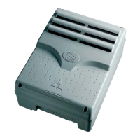
Steps for positioning and securing the control panel enclosure.

Snap and Secure Cover

Instructions for attaching and securing the cover.

Related product manuals