EasyManua.ls Logo

CAME ZC3 - User Manual

CAME ZC3
17 pages
Print Icon
To Next Page IconTo Next Page
Loading...
Documentazione
Tecnica
S33
rev. 2.2
09/2001
©
CAME
CANCELLI
AUTOMATICI
319S33
SCHEDA COMANDO
CONTROL BOARD
CARTE DE COMMANDE
STEUERPLATINE
TARJETA DE MANDO
SERIE Z |
Z SERIES
/ SÉRIE Z |
BAUREIHE Z |
SERIE Z
ZC3
CANCELLI AUTOMATICI
CARATTERISTICHE GENERALI
Descrizione quadro
Il quadro elettrico ZC3 è adatto al
comando di una automazione per
portoni industriali scorrevoli della serie
C e F3000, alimentati a 230V con
potenza fino a
600W, frequenza 50÷60 Hz.
Progettato e costruito interamente dalla
CAME S.p.A., risponde alle vigenti
norme UNI 8612. Contenitore in ABS
con grado di protezione IP54, dotato di
presa per il riciclo d’aria e completo di
trasformatore.
Il circuito va alimentato
con tensione di 230V
(a.c.) nei morsetti L1- L2 e protetto in
ingresso con due fusibili da 5A,
mentre i dispositivi di comando a
bassa tensione sono protetti con
fusibile da 1A.
La potenza complessiva degli
accessori (24V) non deve superare i
20W.
Il quadro include la funzione di spunto
manovra. Questa funzione si attiva in
fase di inizio apertura e chiusura del
portone.
ITALIANO
240 mm
120 mm
145 mm
320 mm

Other manuals for CAME ZC3

Question and Answer IconNeed help?

Do you have a question about the CAME ZC3 and is the answer not in the manual?

CAME ZC3 Specifications

General IconGeneral
BrandCAME
ModelZC3
CategoryControl Panel
LanguageEnglish

Summary

Product Overview and General Characteristics

Control Panel Description

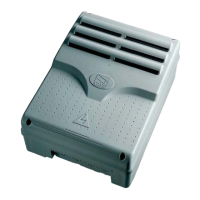
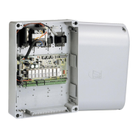
Details the ZC3 electric panel's suitability for industrial sliding gates and its construction.

Safety Features

Explains the safety functions, including photocell integration and obstacle detection.

Adjustments and Settings

Trimmer Adjustments

Explains adjustments for operating time, automatic closing, and partial opening.

Electrical Connections

Terminal Block Functions

Details the purpose of each terminal block for power, motor, and outputs.

Installation and Mounting

Cabinet Assembly Steps

Step-by-step guide for assembling the control panel cabinet and cover.

Safety System Testing

Photocell Function Test

Procedure to verify the efficiency of safety photocells after commands.

DIP-Switch Configuration (1-10)

DIP-Switch Configuration (11-20)

Two Combined Motors Connection

Related product manuals