This document outlines the installation and operational guidelines for the CAME ZA3N control panel, designed for 230V gearmotors in swing gate automation systems. It emphasizes safety, proper installation procedures, and detailed instructions for connecting and programming the device.
Function Description
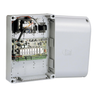
The CAME ZA3N is a multifunction control panel specifically engineered for automating swing gates. It operates on a 24V supply for control devices and accessories, ensuring a safe low-voltage environment for these components. The control panel is equipped with quick-fuse protection for all connections, enhancing safety and ease of maintenance.
Key functions provided and controlled by the ZA3N card include:
- Automatic Closing: The system can be configured to automatically close the gate after a set period following an opening command. This feature enhances convenience and security.
- Pre-Flashing: Before the gate begins to move, a connected movement indicator light will pre-flash, providing a visual warning to pedestrians and vehicles.
- Obstruction Detection: The control panel incorporates a safety mechanism that detects obstructions when the gate is not moving. This prevents damage to the gate and potential injury.
- Operator Torque Adjustment: Users can adjust the torque of the connected operator, allowing for fine-tuning based on the gate's weight and operational needs.
- Opening Jolt: An "opening jolt" feature is available, where the gate leaves briefly jolt inwards at the beginning of an opening command. This is particularly useful for releasing electric locks, ensuring smooth operation.
The ZA3N supports various settable control modes to suit different operational requirements:
- Opening/Closing: Standard operation where the gate opens and closes.
- Opening/Closing in Maintained Action: Requires continuous input from a command device for the gate to move.
- Partial Opening: Allows for the partial opening of one gate leaf, typically for pedestrian access.
- Total Stop: Immediately halts all gate movement.
The control panel also integrates with photocells, which act as safety devices. Upon detecting an obstruction, photocells can trigger different responses:
- Reopening: If the gate is closing, it will reopen completely.
- Reclosing or Partial Stop: If the gate is opening, it can either reclose or perform a partial stop.
- Partial Stop: Halts movement if an obstruction is detected during opening or closing.
Usage Features
The ZA3N control panel offers several adjustable parameters through trimmers and DIP-switches, allowing for flexible configuration:
- Automatic Closing Time (ACT): A dedicated trimmer allows adjustment of the automatic closing time from a minimum of 1 second to a maximum of 120 seconds.
- Operating Time (OT): The operating time of the gate can be set from 10 seconds to 120 seconds using a specific trimmer.
- Motor 2 Closing Delay (TRM2): This trimmer adjusts the closing delay for Motor 2 (the second gate leaf) from 0 to 15 seconds. Simultaneously, it controls the partial opening time from 0 to 30 seconds.
The control panel supports connections for various external devices:
- Gate Open Warning Lights: These lights indicate when the gate is open, enhancing safety.
- Cycle Lights: These lights illuminate the driveway during gate operation, staying lit from the start of opening until the gate is fully closed (including automatic closing time). If automatic closing is not enabled, they remain lit only during movement.
- Electric Lock: An electric lock can be connected to terminals 11-S, providing additional security.
Radio control functionality is enabled by fitting an AF radio-frequency card into a dedicated slot on the control board. The system allows for memorizing transmitter buttons for direct commands (CH1) and for controlling accessory devices (CH2).
Command and control devices can be connected for various operations:
- Stop Button (N.C. contact): Commands the gate to stop and excludes the automatic closing cycle. If unused, terminals 1-2 must be short-circuited.
- Key-Switch Selector and/or Opening Button (N.O. contact): Commands the gate to open.
- Key-Switch Selector and/or Partial Opening Button (N.O. contact): Commands the partial opening of one gate leaf (gearmotor M2) for pedestrian passages.
- Key-Switch Selector and/or Closing Button (N.O. contact): Commands the gate to stop.
- Key-Switch Selector and/or Command Button (N.O. contact): Commands both opening and closing. Depending on DIP-switch settings, pressing the button or turning the key can reverse movement or stop the gate.
Safety devices, such as photocells and sensitive safety-edges, can be connected for:
- Reopening during closing (N.C. contact): If an obstruction is detected while closing, the gate reverses movement until fully open.
- Reclosing during opening (N.C. contact): If an obstruction is detected while opening, the gate reverses movement until fully closed.
- Partial-stop (N.C. contact): Stops movement and sets up for automatic closing if an obstruction is detected.
Maintenance Features
The manual emphasizes the importance of proper installation and regular checks to ensure the system's longevity and safety.
- Cable Management: Electrical cables must be run through appropriate tubes or conduits to protect against mechanical damage and prevent contact with parts that may heat up.
- Power Supply Cut-off: A suitable dual-pole cut-off device compliant with installation rules must be fitted along the power supply to completely cut off power under category III surcharge conditions.
- Component Replacement: If the power-supply cable is damaged, it must be replaced by the manufacturer, a licensed technical-assistance center, or duly trained staff to prevent risks. The manufacturer explicitly states that using non-original parts will void the warranty.
- Disassembly and Disposal: The manual provides clear instructions for dismantling and disposing of the product and its components. Packaging materials should be separated for recycling. Other components, such as control boards, batteries, and transmitters, which may contain hazardous pollutants, must be disposed of by authorized, certified professional services. This ensures environmental responsibility.
- Documentation: The manual should be stored in the technical folder along with other system device manuals and handed over to end-users, ensuring they have access to operating instructions for the final machinery.